Interactive polarization-preserving projection display
A polarization-maintaining and interactive technology, applied in the field of input information, which can solve the problems of environmental signal interference and shielding of input signals.
- Summary
- Abstract
- Description
- Claims
- Application Information
AI Technical Summary
Problems solved by technology
Method used
Image

Examples
example 1
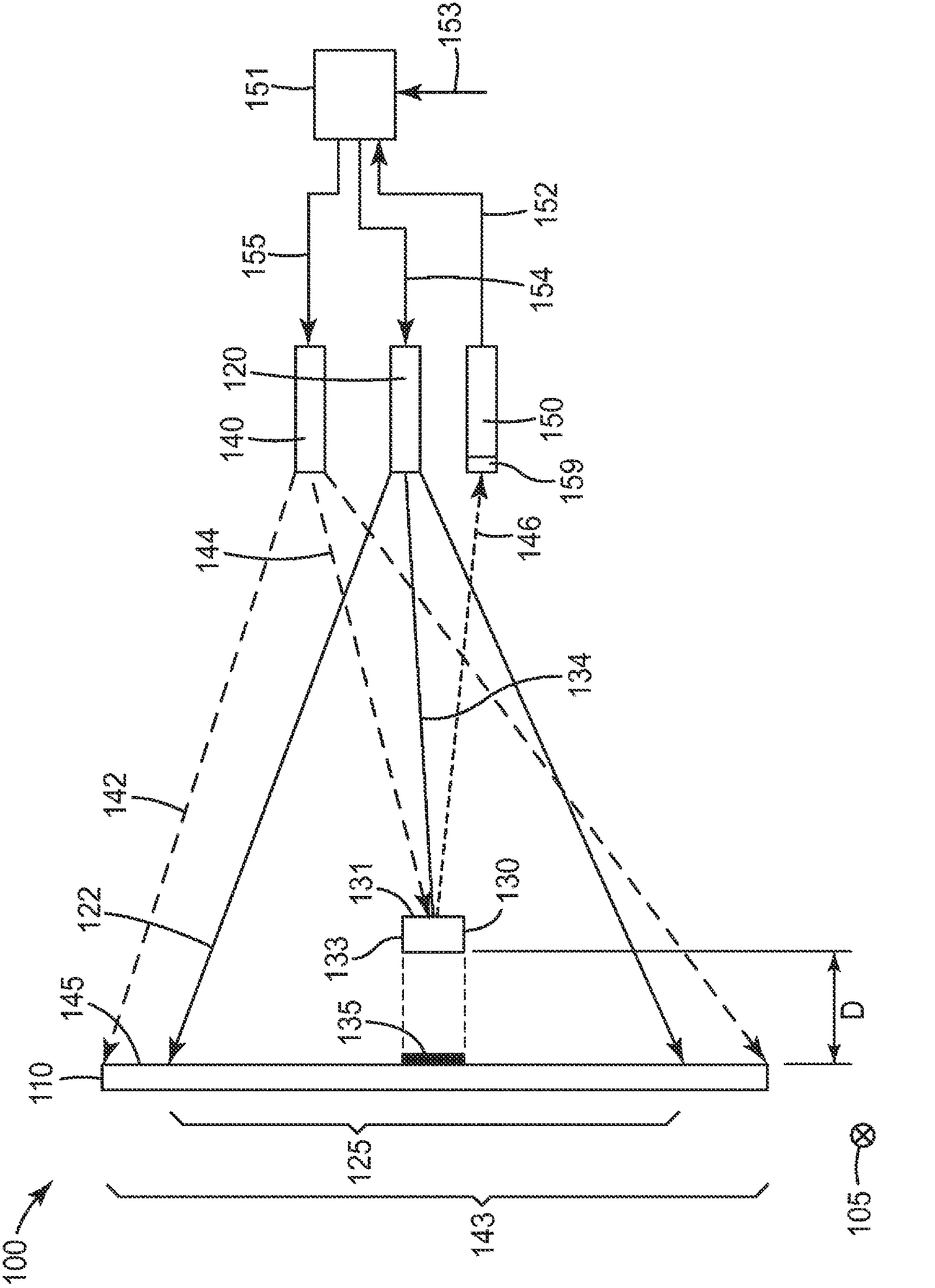
[0091] Example 1: Interactive Display with Polarization Selection Screen
[0092] Interactive displays may include projectors with visible output. The visible output can be projected on a polarization maintaining reflective screen. Infrared Light The polarization preserving screen may be illuminated with p-polarized infrared light invisible to humans. P-polarized infrared light can be generated with infrared light emitting diodes (LEDs) and polarizing films (eg, reflective polarizers, absorbing polarizers, etc.). The reflective polarizer film can be any known reflective polarizer, such as a MacNeille polarizer, a wire grid polarizer, a multilayer optical film polarizer, or a circular polarizer such as a cholesteric liquid crystal polarizer. An infrared sensor, such as an infrared-sensing camera that detects a bright infrared spot, is pointed at the polarization-maintaining screen. Infrared sensors can be retrofitted from digital signal processing (DSP) "Wii" remote or w...
example 2
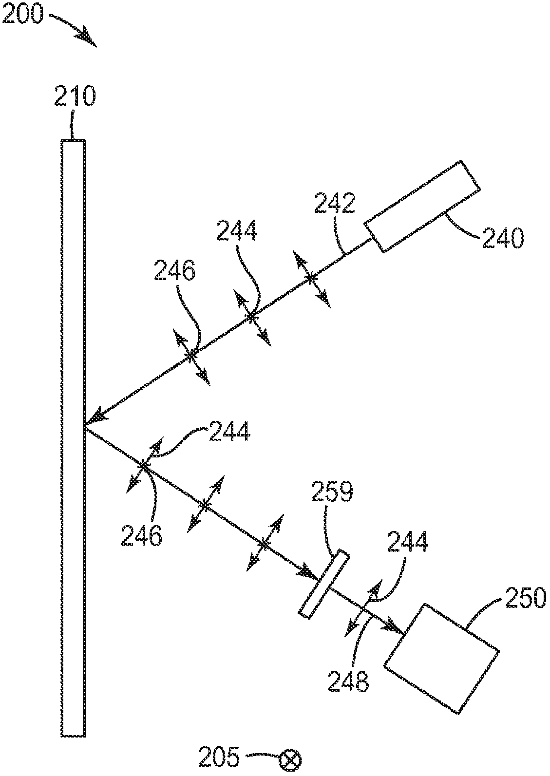
[0095] Example 2: Interactive display without polarization maintaining screen
[0096] The same configuration as presented in Example 1 was used, but the polarization maintaining screen was replaced by a diffusing screen (eg a diffusing wall surface). Alternatively, as described in Example 1, a polarization maintaining retroreflective marker was used.
[0097] Project the visible keypad onto a diffuse wall. Infrared cameras cannot sense visible images, making them immune to projected images. The image field on the wall is also filled with infrared light. The illuminating infrared light is largely diffusely reflected by the wall, and has a mixed polarization state, which allows the infrared camera to sense very little infrared illumination. Due to the polarization analyzer arranged above the infrared camera, any unwanted ambient infrared illumination is typically reduced in half. Thus, an infrared sensor detects a generally dark field with no bright infrared spots. A ret...
example 3
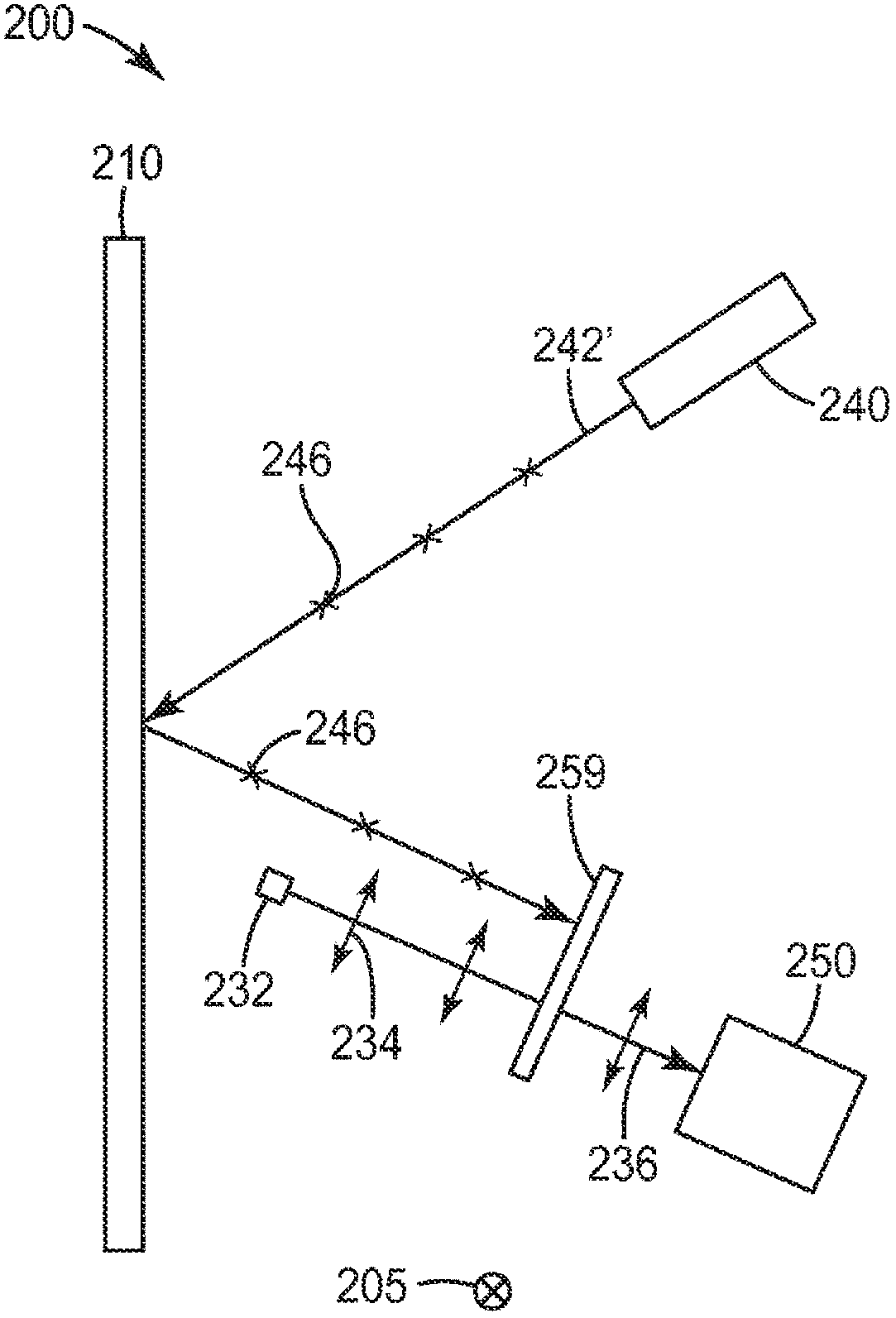
[0098] Example 3: Interactive Display with Dual Retroreflective Markers
[0099] The same configuration was used as provided in Example 2, but with an additional infrared illuminator to flood the polarization maintaining screen with horizontally polarized light. The two infrared illumination sources can be independently activated as required. In some cases, it can be used to quickly alternate between various infrared illumination states. States may include vertically polarized infrared illumination only, horizontally polarized infrared illumination only, simultaneous horizontal and vertical infrared illumination, and non-intentional infrared illumination. It may be useful to quickly sequence multiple infrared illumination states to achieve a sensing speed that is considered substantially instantaneous or simultaneous. Each of the several sensors may include a polarization analyzer oriented to a different polarization direction such that each sensor detects a signal only wh...
PUM
 Abstract
Description
Claims
Application Information
 - R&D Engineer
- R&D Manager
- IP Professional
- Industry Leading Data Capabilities
- Powerful AI technology
- Patent DNA Extraction
Browse by: Latest US Patents, China's latest patents, Technical Efficacy Thesaurus, Application Domain, Technology Topic.
© 2024 PatSnap. All rights reserved.Legal|Privacy policy|Modern Slavery Act Transparency Statement|Sitemap