Medicament delivery device

A technology for delivery equipment and drugs, applied in the direction of hypodermic injection devices, etc., which can solve the problems of user confusion and not knowing whether the drug delivery equipment is ready for use, etc.

Inactive Publication Date: 2013-07-31
SHL GRP AB
View PDF5 Cites 4 Cited by
  • Summary
  • Abstract
  • Description
  • Claims
  • Application Information

AI Technical Summary

Problems solved by technology

Lack of an indicator device can confuse users as t

Method used


Image

  • Medicament delivery device
  • Medicament delivery device
  • Medicament delivery device

Examples


Embodiment Construction

[0035] As should be noted, in this application, when the term "distal part / end" is used, this refers to the part / end of the delivery device or its components which is located furthest from the drug delivery site of the patient. Accordingly, when the term "proximal portion / proximal end" is used, this refers to the portion / end of the delivery device or a component thereof that is located closest to the drug delivery site of the patient.

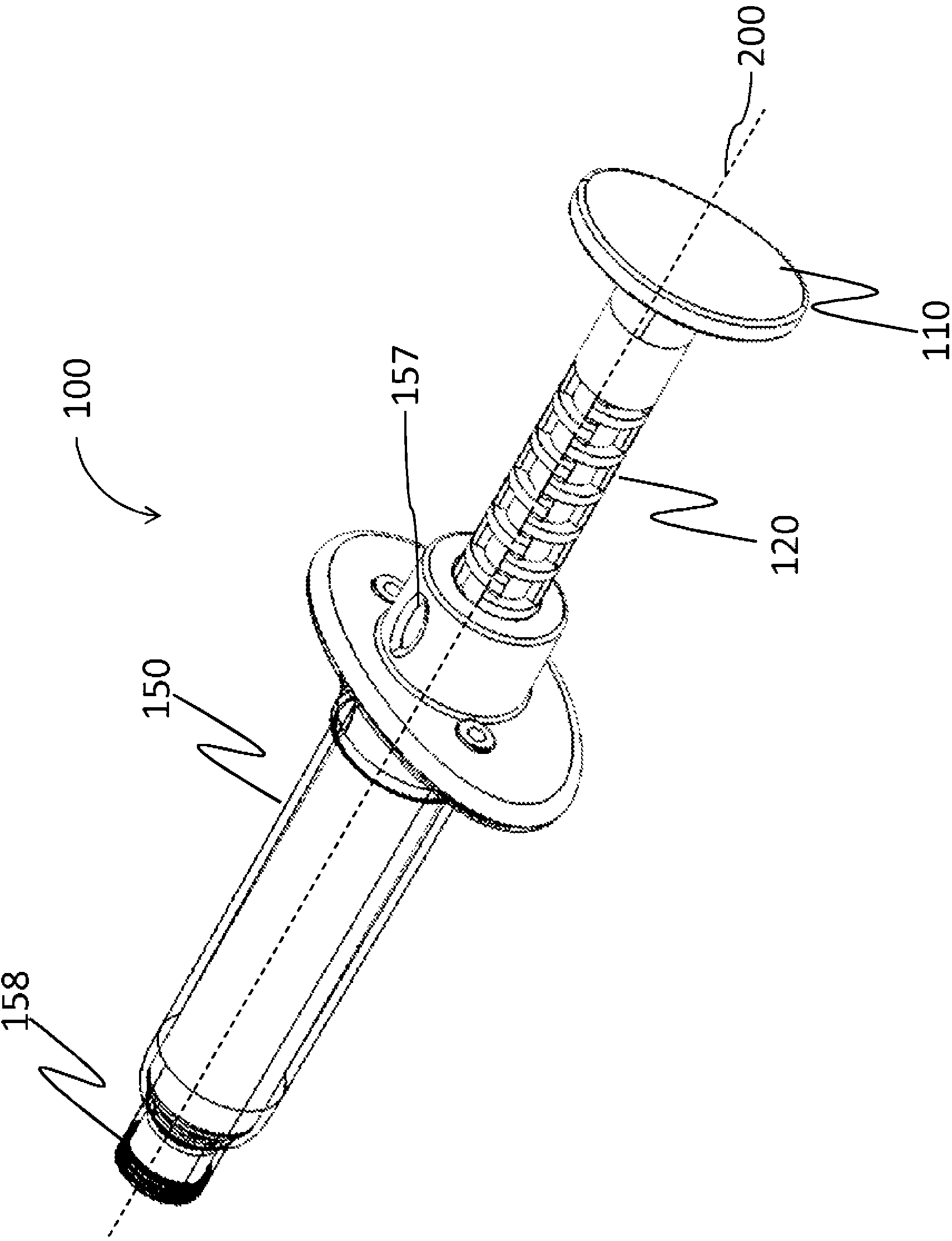
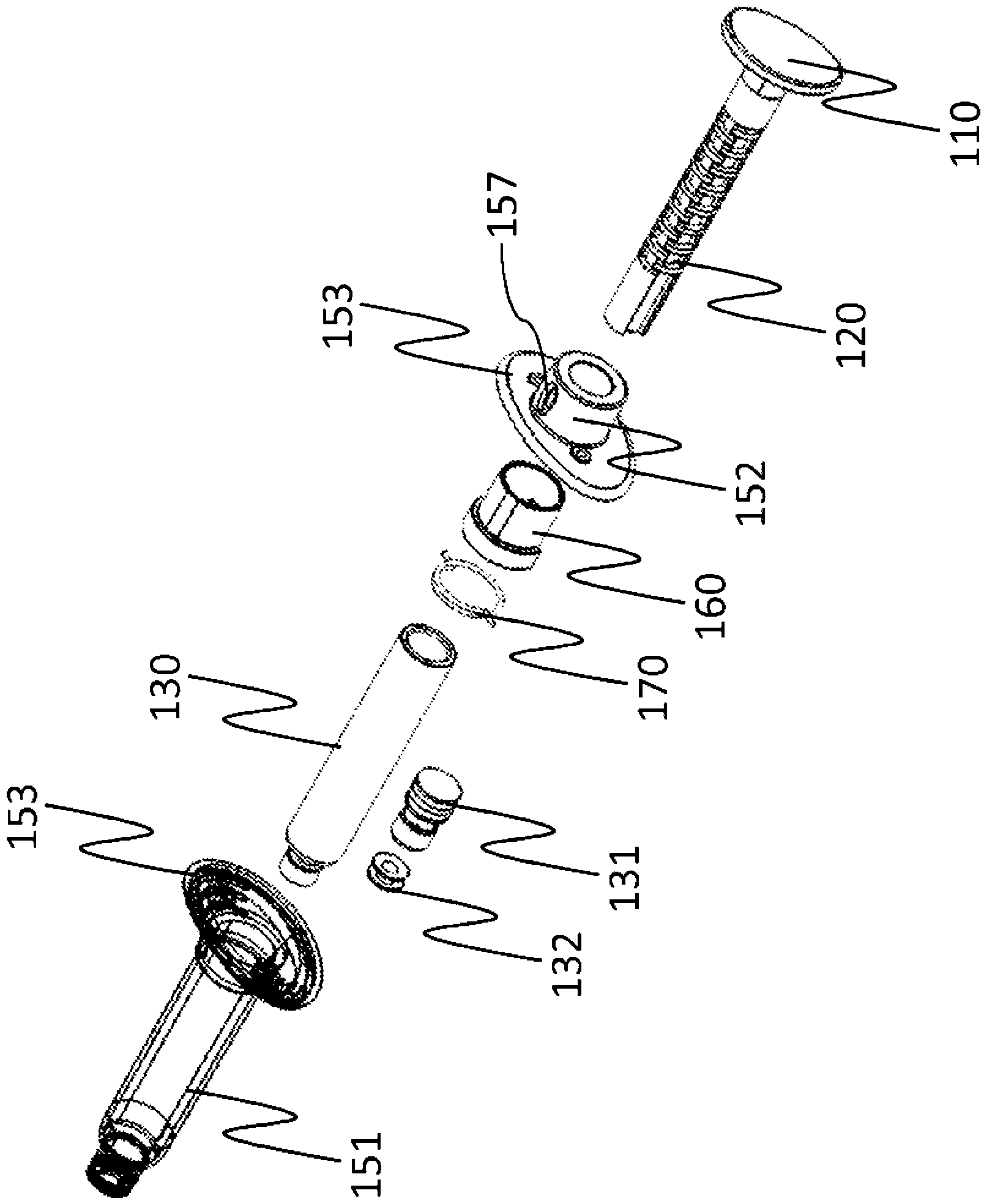
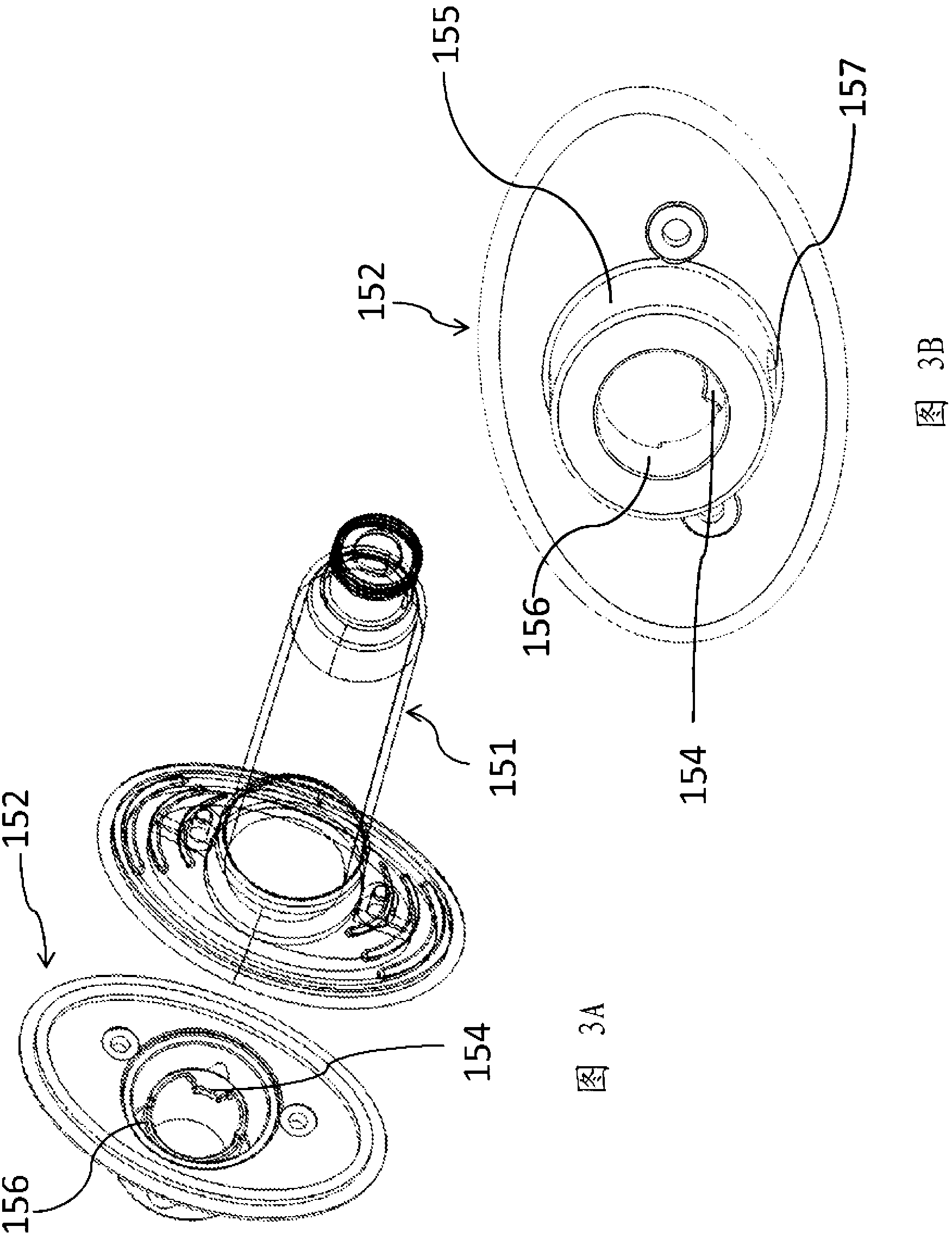
[0036] The present invention relates to a drug delivery device comprising an elongated housing 150 extending along an axis 200 for containing a drug, a coaxially extending plunger rod 120; 220 mounted within the housing 150 to Axially displaceable for expelling successive doses of medicament, and rotatable about an axis 200, the plunger rod 120; 220 and the housing 150 comprise first guiding means 123; It is adapted to guide the plunger rod 120; 220 inside the housing 150, in order: from a ready-to-use position to a non-ready-to-use position, i...


PUM


Abstract

Provided is a medicament delivery device comprising an axially elongated housing, a coaxially extending plunger rod mounted with in the housing for expelling successive doses of medicament and rotatable about the axis. The plunger rod can be axially displaced from a ready-to-use position for expelling a dose of medicament to a non-ready-to-use position axially spaced from said ready-to-use position along the axis, and from said non-ready-to use position to a subsequent ready-to-use position angularly spaced from said non-ready-to use position about the axis The device further comprises an indicator member displaceably mounted onto the housing between a first angular position indicative of the ready-to-use positions and a second angular position indicative of the non-ready-to use positions.

Description

technical field [0001] The present invention relates to a medicament delivery device, and more particularly to a medicament delivery device comprising a support mechanism for conveniently indicating activation or deactivation of the device when a user intends to inject a predetermined amount of medicament. Background technique [0002] Traditionally with conventional hypodermic syringes, the practitioner or user must stop depressing the plunger based on visual feedback, usually from a scale on the hypodermic syringe. As a result, repeated dose injections with high accuracy and / or precision are difficult to perform. [0003] In US 5,318,544 a syringe for metering precise quantities of fluids without the use of visual volume scales is disclosed. This document discloses a syringe container adapted to receive a plunger comprising a plurality of stop surfaces which are angularly and linearly displaced about the plunger longitudinal axis. Translation of the plunger brings the fi...

Claims


Application Information

Patent Timeline
IPC IPC(8): A61M5/315
CPCA61M5/31511A61M5/31505A61M5/31595
Inventor M.古斯塔夫森S.鲁夫
Owner SHL GRP AB
Why Eureka
Try Eureka