Operation unit of engine

a technology of operation unit and engine, which is applied in the direction of engine starter, machine/engine, ignition safety means, etc., can solve the problems of troublesome maintenance of parts, difficulty in ensuring the accuracy of parts, and complicated operation procedures, so as to secure the safety of the operation unit, secure the effect of further safety and secure the effect of eliminating the erroneous actuation of the engin

Inactive Publication Date: 2006-12-26
HUSQVARNA ZENOAH
View PDF6 Cites 2 Cited by
  • Summary
  • Abstract
  • Description
  • Claims
  • Application Information

AI Technical Summary

Benefits of technology

[0010]An object of the present invention is to provide an operation unit which can securely avoid an erroneous operation and an erroneous actuation tending to be generated between the start switch of the self-starter and the throttle operating lever as mentioned above, and in which the start switch and the throttle operating lever are integrally installed, with an extremely simple structure.
[0016]As mentioned above, according to the present invention, it is possible to do away with the troublesome operation so as to securely eliminate the erroneous actuation of the engine due to the erroneous operation, and it is possible to secure a further safety, based on the simple structure obtained only by installing the normally used start switch, the throttle operating lever, two terminals of the start motor, the contact element with which these two terminals are simultaneously brought into contact, and the interlocking means as one unit in the single box. The effects which the present invention exerts are considerably great.

Problems solved by technology

However, the mechanism and the operating procedure are extremely complicated and troublesome, an accuracy of the parts is required, and it is troublesome to maintain the parts.
Further, the erroneous operation tends to be generated in the throttle operating lever and the start and stop operating lever, it is hard to simply start and stop the engine itself, and a smooth operation is expected only by persons of experience in the art.

Method used


Image

  • Operation unit of engine
  • Operation unit of engine
  • Operation unit of engine

Examples


Embodiment Construction

[0025]A description will be specifically given below of a preferable embodiment in accordance with the present invention based on an illustrated embodiment.

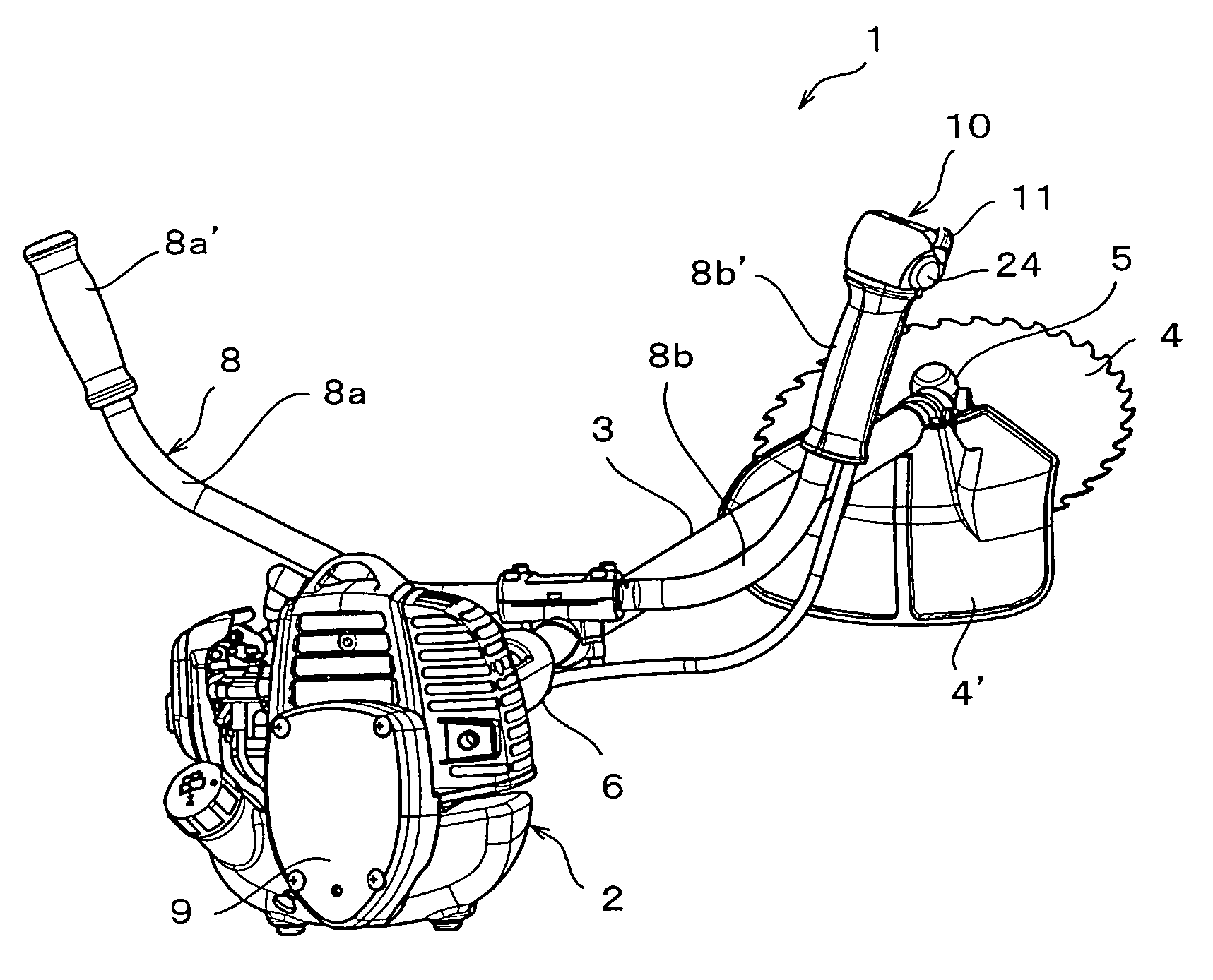
[0026]FIG. 1 is a bush cutter provided with a self-starter corresponding to a typical embodiment in which an operation unit according to the present invention is attached to a handle portion.

[0027]The bush cutter 1 mentioned above is provided with an engine portion 2, a long lever 3 being a long operation lever, and a rotary blade 4. A long driven shaft (not shown) constituted of a metal rod is inserted to the long lever 3, and a base end portion of the long lever 3 is coupled to the rotary blade 4 via a gear housing 5. A bevel gear mechanism (not shown) is arranged in an inner portion of the gear housing 5. On the other hand, a base end portion of the long lever 3 is coupled to the engine portion 2 via a clutch housing (not shown). Further, a grip 6 doubling as a suspended portion suspended to a part of a harness (not shown) is ...


PUM


Abstract

The invention provides an operation unit of an engine provided with a throttle operating lever operating a throttle valve of the engine from an idle position to a full-open position, two terminals connected to an inner side of a drive circuit of a start motor, a contact element interposed between the terminals and setting a region between both the terminals to a conduction state or a non-conduction state, and a start switch making the region between the terminals conductive or non-conductive, the operation unit further comprising interlocking means for relatively moving a contact position between at least one terminal of the two terminals and the contact element in correspondence to an operation amount of the throttle operating lever, and the terminals and the contact element being brought into contact with each other only at a time when the throttle operating lever is at an idle position.

Description

BACKGROUND OF THE INVENTION[0001]1. Field of the Invention[0002]The present invention relates to an operation unit of an engine which can be applied to various working devices provided with a self-starter using an engine as a source of power such as a trimmer, a chain saw, a rotation saw or the like, or a power spreader, various farm working machines or the like, and more particularly relates to an operation unit of an engine based on a simple mechanism which eliminates an erroneous operation of a start switch.[0003]2. Description of the Related Art[0004]An engine provided with a self-starter actuates a start motor by operating a start switch, and starts the engine based on the actuation. A rotation speed of the engine is controlled by operating a throttle lever so as to control an opening degree of a throttle valve via a control wire. When the rotation speed of the engine reaches a predetermined rotation speed, a clutch within a clutch housing engages so as to start an actuation of...

Claims


Application Information

Patent Timeline
Patent Type & Authority Patents(United States)
IPC IPC(8): F02N11/08
CPCF02D11/02F02N11/10F02P11/04F02B63/02
Inventor ONO, RYOUONIWA, TAKASHIMIYASHITA, SATOSHI
Owner HUSQVARNA ZENOAH
Why Eureka
Try Eureka