Operation unit of engine

a technology of operation unit and engine, which is applied in the direction of engine starter, electric motor starter, machine/engine, etc., can solve the problems of troublesome maintenance of parts, difficulty in adjusting the operation procedure, so as to prevent the engine and the working device from being carelessly actuated

Inactive Publication Date: 2007-01-30
HUSQVARNA ZENOAH
View PDF4 Cites 4 Cited by
  • Summary
  • Abstract
  • Description
  • Claims
  • Application Information

AI Technical Summary

Benefits of technology

[0010]An object of the present invention is to provide an operation unit which can securely avoid an erroneous operation and an erroneous actuation tending to be generated between the start switch of the self-starter and the throttle operating lever as mentioned above, and in which the start switch and the throttle operating lever are integrally installed, with an extremely simple structure.
[0017]Further, as in the preferable embodiment mentioned above, if the shielding portion is provided in a part of the throttle operating lever rotating around one end serving as the rotation center in the switch box, the start switch is placed on a rotation locus thereof, and the shielding portion is formed in such a shape and at such a position that the shielding portion always covers the upper surface of the operation surface of the start switch when the shielding portion existing at a reference position (an idle position) is moved, the shielding portion shields the operation surface of the start switch at the same time of rotating the throttle operating lever. Accordingly, it is possible to securely disenable to operate the start switch, and it is possible to prevent the engine and the working devices from being carelessly actuated.

Problems solved by technology

However, its mechanism and operating procedures are extremely complicated and troublesome, an accuracy of parts is required, and it is troublesome to maintain the parts.
Further, the erroneous operation tends to be generated in the throttle operating lever and the start and stop operating lever, it is hard to simply start and stop the engine itself, and a smooth operation is expected only by persons of experience in the art.

Method used


Image

  • Operation unit of engine
  • Operation unit of engine
  • Operation unit of engine

Examples


Embodiment Construction

[0025]A description of a preferable embodiment in accordance with the present invention will be specifically given below based on an illustrated embodiment.

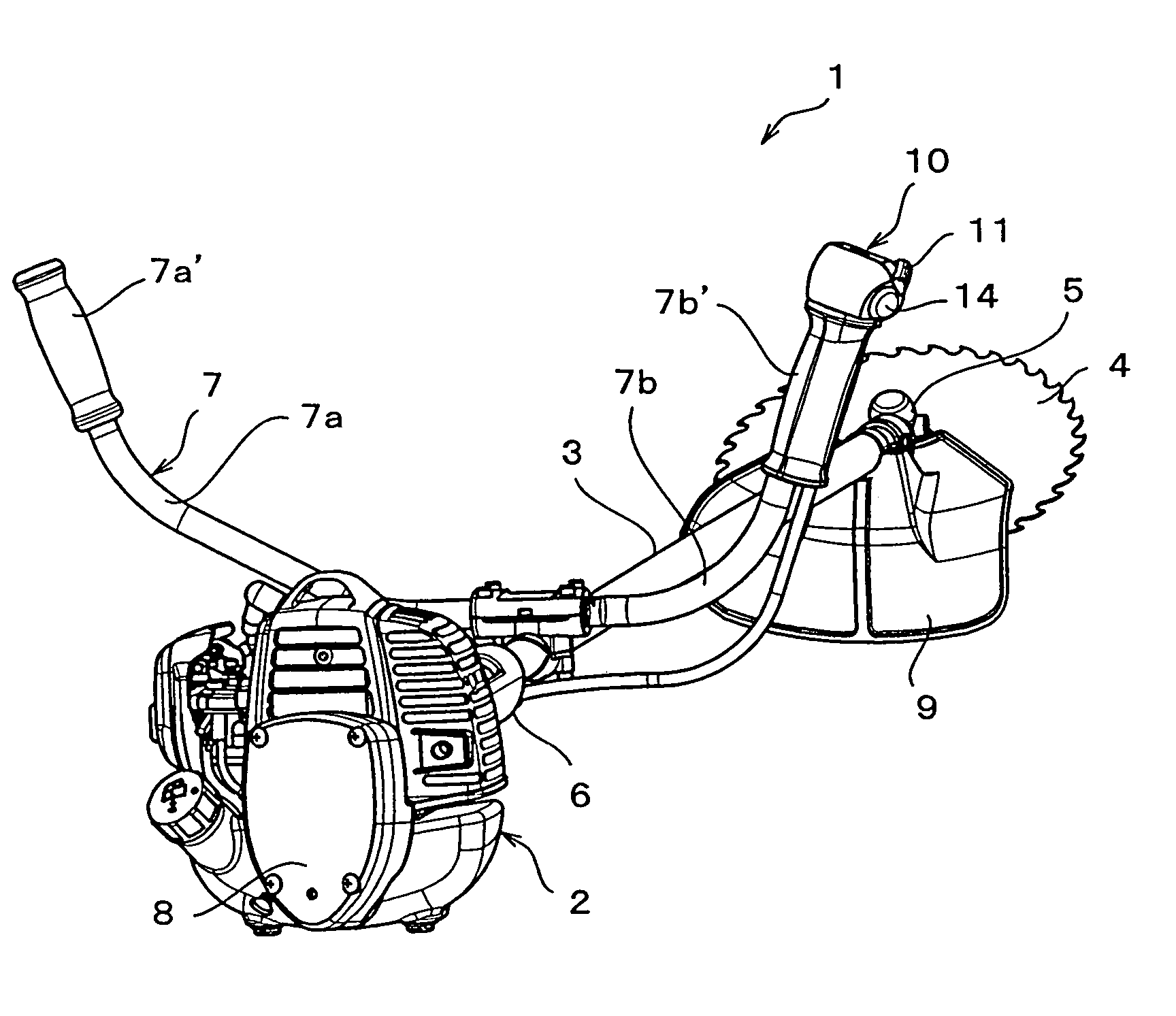
[0026]FIG. 1 is a bush cutter provided with a self-starter corresponding to a typical embodiment in which an operation unit according to the present invention is attached to a handle portion.

[0027]The bush cutter 1 mentioned above is provided with an engine portion 2, a long lever 3 corresponding to a long operation lever, and a rotary blade 4. A long driven shaft (not shown) constituted of a metal rod is inserted into the long lever 3, and a base end portion of the long lever 3 is coupled to the rotary blade 4 via a gear housing 5. A bevel gear mechanism (not shown) is arranged in an inner portion of the gear housing 5. On the other hand, a base end portion of the long lever 3 is coupled to the engine portion 2 via a clutch housing (not shown). Further, a grip 6 doubling as a suspended portion suspended to a part of a harness (n...


PUM


Abstract

An operation unit is provided with an engine operation box storing a control operation portion controlling an opening degree of a throttle valve and a start switch terminal connected to a start motor; a throttle operating lever for controlling the opening degree from an idle position to a full-open position; and a start switch connecting and disconnecting the start switch terminal, wherein the throttle operating lever has a switch shielding portion which enables to operate the start switch without an interference between the throttle operating lever and an operating portion of the start switch when the throttle operating lever is at an idle position, and disables to operate the start switch by shielding at least a part of the operating portion of the start switch by means of a part of the throttle operating lever when the throttle operating lever is operated to be apart from the idle position.

Description

BACKGROUND OF THE INVENTION[0001]1. Field of the Invention[0002]The present invention relates to an operation unit structured by unitizing a throttle operating lever of an engine and a start switch which can be applied to various working devices provided with an engine as a source of power and a self starter such as a trimmer, a chain saw, a rotation saw or the like, or a power spreader, various farm working machines or the like, and more particularly to an operation unit of an engine which eliminates an erroneous operation of the start switch based on a simple mechanism.[0003]2. Description of the Related Art[0004]An engine provided with a self-starter actuates a start motor by operating a start switch, and starts the engine based on the actuation. A rotation speed of the engine is controlled by operating a throttle lever so as to control an opening degree of a throttle valve via a control wire. When the rotation speed of the engine reaches a predetermined rotation speed, a clutch ...

Claims


Application Information

Patent Timeline
Patent Type & Authority Patents(United States)
IPC IPC(8): F02N11/08
CPCF02D11/02
Inventor ONO, RYOUONIWA, TAKASHIHOKARI, HIROSHI
Owner HUSQVARNA ZENOAH
Why Eureka
Try Eureka