Sliding door lock with handle

A sliding door and door lock technology, applied in building locks, wing handles, door/window accessories, etc., can solve the problems of inconvenience and difficulty in pulling out, etc., and achieve the effect of simple door lock structure.

Active Publication Date: 2013-08-07
SUZHOU WANSHENGYI HARDWARE LOCK
View PDF4 Cites 2 Cited by
  • Summary
  • Abstract
  • Description
  • Claims
  • Application Information

AI Technical Summary

Problems solved by technology

However, for this type of sliding door, when the door is in the middle o

Method used


Image

  • Sliding door lock with handle
  • Sliding door lock with handle

Examples


Embodiment Construction

[0014] The present invention will be further described in detail below in conjunction with the accompanying drawings, so that those skilled in the art can implement it with reference to the description.

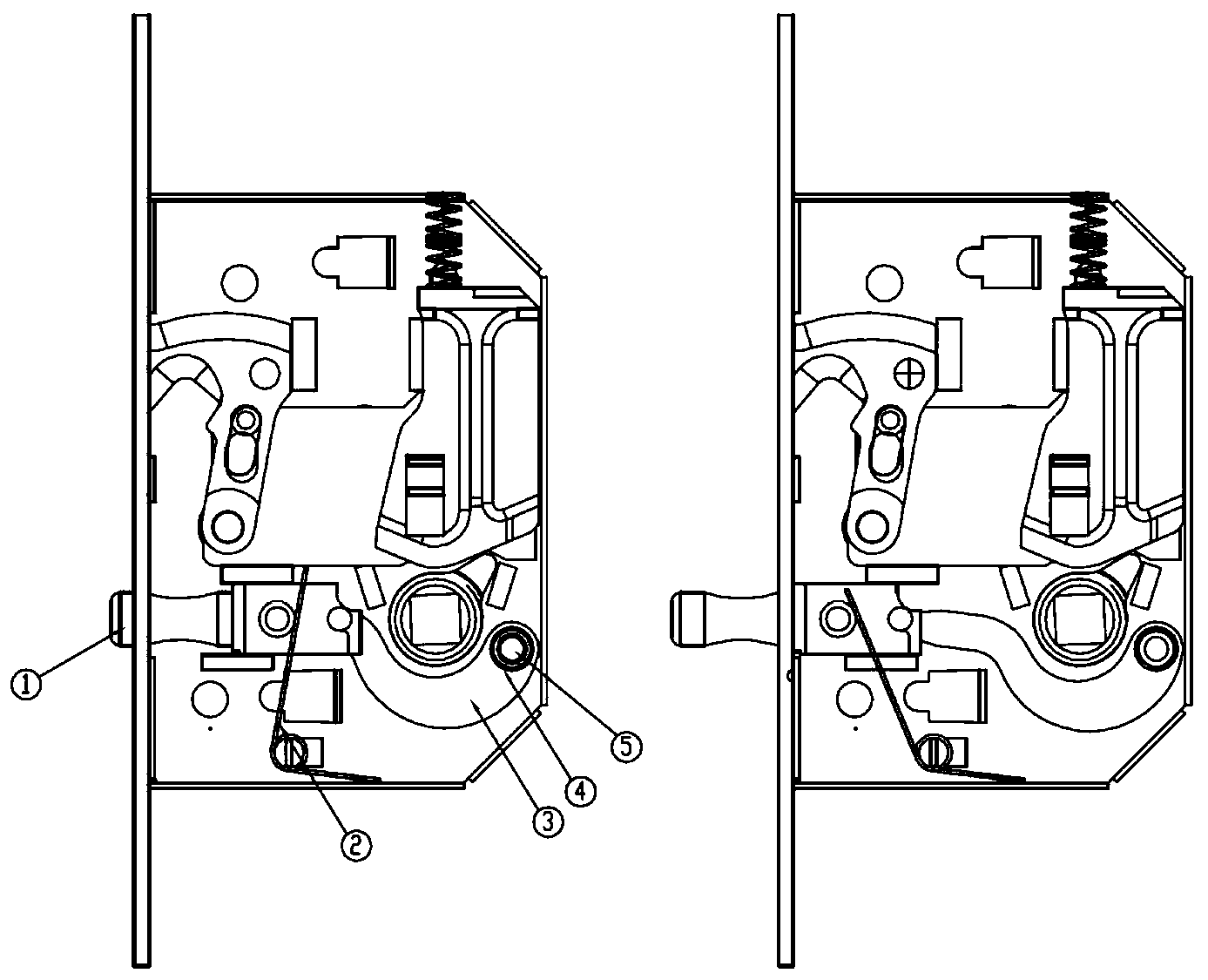
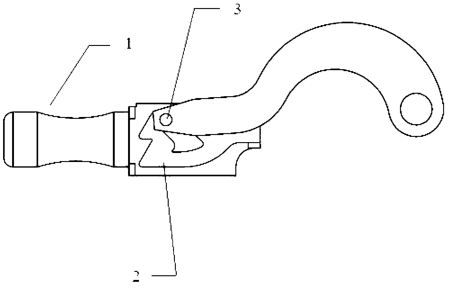
[0015] see figure 1 , figure 2 As shown, it illustrates a sliding door lock with a handle according to an embodiment of the present invention. Inside, and connected with the handle rod 1, one side of the handle unit includes a concave groove and a convex stop located in the middle of the concave groove, the convex stop divides the concave groove into an annular slide groove 2, and the other side A pressure block is provided; a guide plate, one end of which is pivotally connected to the door lock body, and the other end has a protrusion 3, and the protrusion 3 is embedded in the chute 2; a compression spring, one end of which is fixed in the door lock body , and the other end collides with the pressure block of the handle unit, and applies a force to the handle unit to exte...


PUM


Abstract

The invention discloses a sliding door lock with a handle. The sliding door lock comprises a door lock body, a handle rod (1) extending and retracting from the door lock body, a handle unit arranged in the door lock body and connected with the handle rod (1), a guiding plate and a pressure spring. A recessed groove and a protruding stop block in the middle of the recessed groove are arranged on one side of the handle unit, the protruding stop block divides the recessed groove into an annular sliding groove (2), and a pressing block is arranged on the other side of the handle unit. One end of the guiding plate is in pivot connection in the door lock body, the other end of the guiding plate is provided with a protrusion (3), and the protrusion (3) is embedded in the sliding groove (2). One end of the pressure spring is fixed in the door lock body, and the other end of the pressure spring butts against the pressing block of the handle unit and exerts force on the handle unit to stretch the handle rod (1) out from the door lock body. Stretching out and retraction of the handle rod (1) are achieved by enabling the protrusion (3) to slide along a semi-ring on one side of the annular sliding groove (2). The sliding door lock with the handle is simple in structure and convenient to operate.

Description

technical field [0001] The invention relates to a door lock, in particular to a sliding door lock with a handle. Background technique [0002] At present, there is a sliding door on the market, a part of the sliding track is embedded in the middle of the wall. When the sliding door is in an open state, the door is located in the wall, which can effectively save space. However, for this type of sliding door, when the door is in the middle of the wall, it is difficult to pull it out, which causes inconvenience to use. In this way, pulling out the door becomes an urgent problem to be solved for this type of sliding door. [0003] Door locks are often installed on such sliding doors. If a retractable handle is installed in the door lock, the dragging problem of such sliding doors can be effectively solved. [0004] Based on the above, the development of a sliding door lock with a handle is necessary. Contents of the invention [0005] Aiming at the deficiencies in the above...

Claims


Application Information

Patent Timeline
IPC IPC(8): E05B65/08E05B1/00
Inventor 戚杞
Owner SUZHOU WANSHENGYI HARDWARE LOCK
Why Eureka
Try Eureka