Method for controlling inflexion point position and upward trend of stopper stiffness and stopper
What is AI technical title?
AI technical title is built by PatSnap AI team. It summarizes the technical point description of the patent document.
A technology of stiffness and stop, applied in the direction of springs, etc., can solve problems such as undisclosed technical solutions
Active Publication Date: 2013-08-14
ZHUZHOU TIMES RUIWEI ANTI VIBERATION EQUIP LTD
View PDF5 Cites 25 Cited by
Summary
Abstract
Description
Claims
Application Information
AI Technical Summary
This helps you quickly interpret patents by identifying the three key elements:
Problems solved by technology
Method used
Benefits of technology
Problems solved by technology
[0005] None of the above-mentioned patent documents discloses a technical solution to solve the above technical problems
Method used
Image
Click on the blue label to locate the original text in one second.
Reading with bidirectional positioning of images and text.
Examples
Embodiment 1
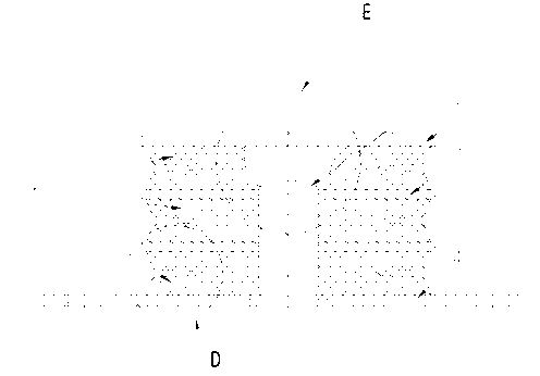
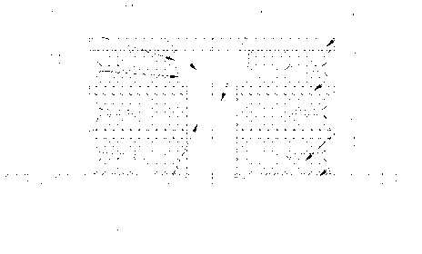
[0029] Embodiment 1: as Figure 1 to Figure 5 As shown, the method for controlling the position of the inflection point of the stop stiffness and the rising trend of the stiffness adopts the combined structure of the inner and outer stops, and separates the metal top plate 1, the elastomer rubber 2, and the elastomer rubber 2 into three layers. The metal partition 3 and the metal bottom plate 4 are sequentially vulcanized to form an outer stopper, the inner stopper 5 is put into the middle cavity 6 of the outer stopper and assembled together with the outer stopper, and each layer is covered by metal partitions. The side parts of the longitudinal section of the elastomer rubber 2 separated by the plate 3 are all provided with a groove structure, and the groove structure includes an arc-shaped groove bottom edge 7, and the symmetrical groove connected with the arc-shaped groove bottom edge 7 The two groove slope sides 8, the symmetrical two circular arc transition sections 9 con...
Embodiment 2
[0041] Embodiment 2: Compared with Embodiment 1, the only difference is that in this embodiment, the N is 2 layers, R is 2mm, α is 3.8 degrees, and L is 19mm; the D is set to 40mm, and r is set is 15mm, the H is set to 15mm, and the S is set to 30mm.
[0042] Figure 7 It is the stiffness curve 1 measured by the stopper stiffness test of the stopper in this embodiment.
Embodiment 3
[0043] Embodiment 3: Compared with Implementation 1, the only difference is: in this embodiment, the N is 4 layers, R is 0.8mm, α is 5 degrees, and L is 30mm.; the D is set to 28mm, r is set to 6mm, the H is set to 12mm, and S is set to 14mm.
[0044] Figure 8 It is the stiffness curve 3 measured by the stopper stiffness test of the stopper in this embodiment.
[0045] pass Figure 6 It can be seen that the stiffness inflection point position B appears at 4.5mm in the curve, that is, when the deformation of the outer stopper=NR=3×1.5=4.5mm, the rigidity inflection point appears. In this embodiment, by setting N as 3 layers and R as the stopper at 1.5 mm, the position where the rigidity inflection point appears is controlled at 4.5 mm.
[0046] pass Figure 7 It can be seen that the stiffness inflection point position A appears at 4 mm in the curve, that is, when the deformation of the outer stop = NR = 2 × 2 = 4 mm, the rigidity inflection point appears. In this embodime...
PUM
Abstract
The invention discloses a method for controlling an inflexion point position and an upward trend of stopper stiffness. According to the method for controlling the inflexion point position and the upward trend of the stopper stiffness, an assembled structure of an inner stopper and an external stopper is adopted; a lateral portion of a longitudinal section of every elastomer rubber layer which is segregated by a metal partition is arranged into a groove structure; the groove structure comprises an arc type groove bottom edge, two symmetrical inclined side edges of the groove, two symmetrical arc transition sections which are connected with the inclined side edges of the groove and two symmetrical inclined top edges of the groove; the two inclined side edges of the groove are connected with the arc type groove bottom edge; the two symmetrical inclined top edges of the groove are connected with the arc transition sections; the inflexion point position of the stiffness is controlled by arranging the number of elastomer rubber layers which are segregated by the metal partition and the arc diameter of the arc type groove bottom edge; the upward trend of the stiffness is controlled by arranging degrees of the groove inclined lateral edges and a horizontal line and the length of the groove inclined lateral edges; changing of stiffness characters and a function of a hard stopper are achieved; and the inflexion point position and the upward trend of the stiffness are accurately controlled.
Description
technical field [0001] The invention relates to a working method of a vibration damping component and its product, in particular to a method for controlling the inflection point position of the stop stiffness and the rising trend of the stiffness and the stop thereof. Background technique [0002] Rubber stopper is a commonly used rubber-metal composite vibration-reducing and limiting element, which can be widely used in various vibration-reducing and limiting places, especially in bogies of urban rail subways. In practical application, it is usually required that the rubber stopper must realize the characteristic of variable stiffness and have the function of hard stopper at the same time. Among the existing rubber stoppers, the most commonly used one is a combined structure, that is, an inner and outer stopper is combined. In the ordinary combined structure, the variable stiffness characteristics and the hard stop function are realized through the mutual contact betwee...
Claims
Application Information
Patent Timeline
Application Date:The date an application was filed.
Publication Date:The date a patent or application was officially published.
First Publication Date:The earliest publication date of a patent with the same application number.
Issue Date:Publication date of the patent grant document.
PCT Entry Date:The Entry date of PCT National Phase.
Estimated Expiry Date:The statutory expiry date of a patent right according to the Patent Law, and it is the longest term of protection that the patent right can achieve without the termination of the patent right due to other reasons(Term extension factor has been taken into account ).
Invalid Date:Actual expiry date is based on effective date or publication date of legal transaction data of invalid patent.
Patent Type & AuthorityApplications(China)
IPC IPC(8): F16F1/371
Inventor罗俊冯万盛王宏
OwnerZHUZHOU TIMES RUIWEI ANTI VIBERATION EQUIP LTD

