Light source module

A light source module and light collection technology, applied in the field of optical devices, can solve the problem of low brightness and achieve the effect of high collimation and high forward brightness

Inactive Publication Date: 2013-08-14
CORETRONIC
View PDF18 Cites 7 Cited by
  • Summary
  • Abstract
  • Description
  • Claims
  • Application Information

AI Technical Summary

Problems solved by technology

However, no matter in the horizontal or vertical direction of the light source module of this structure, the light beam output angle is still distributed in a relatively large range, which makes the brightness of the light source module in the front view direction low

Method used


Image

  • Light source module
  • Light source module
  • Light source module

Examples


no. 1 example

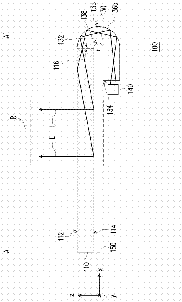
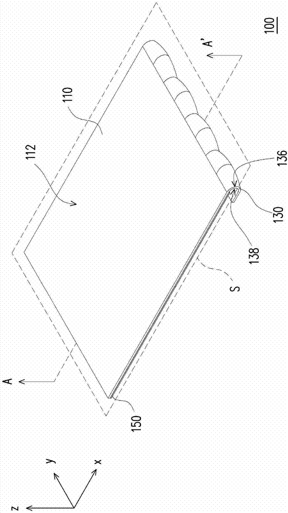
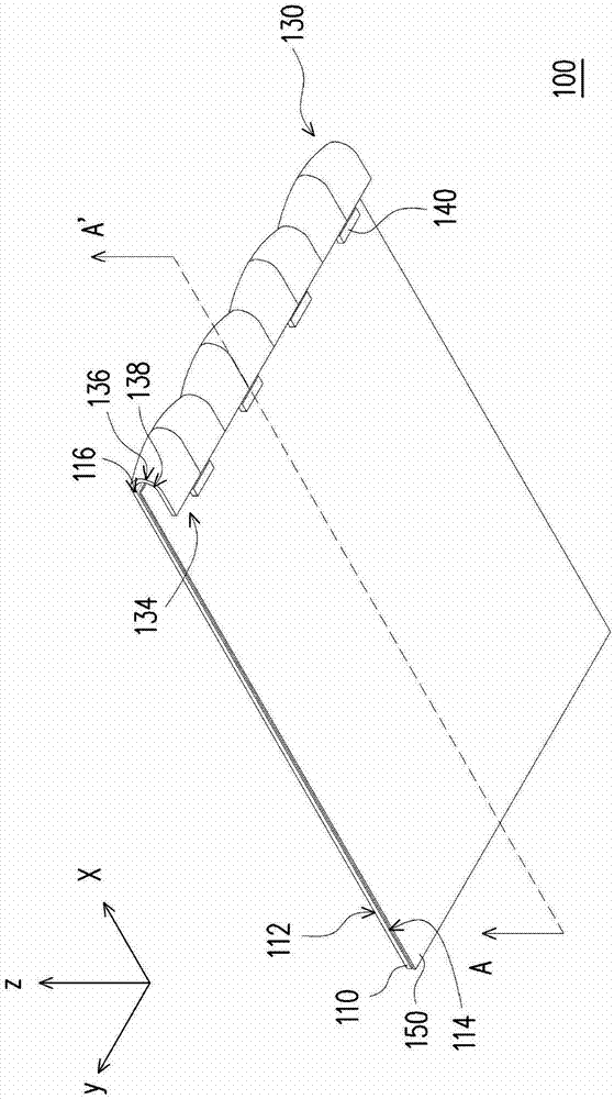
[0081] figure 1 It is a schematic cross-sectional view of the light source module according to the first embodiment of the present invention. figure 2 for figure 1 Stereoscopic view of the light source module. image 3 for figure 1 Stereoscopic view of the light source module. especially, figure 1 yes figure 2 and image 3 Schematic cross-sectional view along section line AA'. Please refer to figure 1 , figure 2 and image 3 , the light source module 100 of this embodiment includes a light guide plate 110 , at least one light collecting structure 130 and at least one light emitting element 140 . figure 2 and image 3 Four light-collecting structures 130 and four light-emitting elements 140 are shown as representatives. One light-collecting structure 130 corresponds to one light-emitting element 140. However, the present invention does not limit the number of light-collecting structures 130 and light-emitting elements 140. The numbers of light-collecting structu...

no. 2 example

[0093] Figure 10 It is a schematic cross-sectional view of the light source module according to the second embodiment of the present invention. Figure 11 for Figure 10 Stereoscopic view of the light source module. Figure 12 for Figure 10 Stereoscopic view of the light source module. especially, Figure 10 With Figure 11 and Figure 12 Schematic cross-sectional view along section line BB'. Please refer to Figure 10 , Figure 11 and Figure 12 , the light source module 100B of this embodiment is similar to the light source module 100 of the first embodiment, so the same components are denoted by the same reference numerals. The main difference between the light source module 100B of this embodiment and the light source module 100 of the first embodiment is that the light collection structure 130B of this embodiment is different from the light collection structure 130 of the first embodiment. In addition, the light source module 100B of this embodiment further i...


PUM


Abstract

A light source module including a light guide plate, a light-collecting structure and a light emitting device for emitting light beams is provided. The light guide plate has a first light emitting surface, a bottom surface, a first light incident surface connecting with the bottom surface and the first light emitting surface, and an optical microstructure unit. The optical microstructure unit includes at least two optical microstructures. Each optical microstructure has a recessing part and a protruding part on the bottom surface. The light-collecting structure has a second light emitting surface connecting with the first light incident surface, a second light incident surface and a reflecting surface connecting with the second light emitting surface and the second light incident surface. A sectional line obtained by sectioning the reflecting surface along a first reference plane includes a first parabola. The reference plane is parallel to the first light emitting surface.

Description

technical field [0001] The invention relates to an optical device, and in particular to a light source module. Background technique [0002] It is known that the light beam emitting angle of the light guide plate has a wide range of distribution. Therefore, in the known light source module, the light guide plate needs to be equipped with an optical film to guide the light beam to the front viewing direction. Taking the current most common light source module structure as an example, the light source module includes a light guide plate with dots, a light-emitting element arranged next to the light guide plate, a diffusion sheet and two rhombus lenses arranged on the light guide plate, and a light guide plate arranged under the light guide plate. reflective sheet. However, no matter in the horizontal or vertical direction, the light emitting angle of the light source module of this structure is still distributed in a relatively large range, which makes the brightness of the ...

Claims


Application Information

Patent Timeline
IPC IPC(8): F21S2/00F21V8/00F21V13/00
CPCG02B6/0036G02B6/0018G02B6/002G02B6/0028G02B6/0031
Inventor 蔡汉文郭铭丰
Owner CORETRONIC
Why Eureka
Try Eureka