Eureka AIR delivers breakthrough ideas for toughest innovation challenges, trusted by R&D personnel around the world.

Linear slides with lubricating oil passages

A technology of linear slide rails and lubricating oil passages, applied in the direction of linear motion bearings, bearings, bearing components, etc., can solve problems such as inability to determine sufficient lubricating oil supply, insufficient lubricating oil supply, and insufficient lubricating oil filling

Active Publication Date: 2015-07-29
HIWIN TECH
View PDF6 Cites 0 Cited by
  • Summary
  • Abstract
  • Description
  • Claims
  • Application Information

AI Technical Summary

Problems solved by technology

[0003] However, with the structural design of the cooperation between the semi-reflux member 4 and the end cover 3, the oil injection passage 32 and the oil passage 33 are all open, and the oil injection passage 32 and the oil passage 33 must be compatible with the sliding block 2. The closed form will be formed only after the end face 23 is matched, and in this kind of matching method, when the lubricating oil is injected into the channel 51 and then enters the oil injection channel 32, the lubricating oil injection method is assisted by a pressurized oil gun or a pump. The injection pressure is too high, and the oil injection channel 32 is parallel to the pressure direction of the lubricating oil, so the lubricating oil directly impacts the end face of the slider 2, so that the lubricating oil seeps out from the gap between the end cover 3 and the end face 23 of the slider 2 like image 3 The component symbol 90 seeps oil, and the leaking position is adjacent to the oil injection channel 32, and the leaking lubricating oil will cause pollution to the surrounding environment; and it will make the lubricating oil insufficient, because if it is an automatic oil supply system, The lubricating oil is replenished at regular intervals, so if the lubricating oil leaks every time, it will cause insufficient lubricating oil supply; in addition, the same is true for manual replenishment. Although it is not regular and quantitative, the installation position of the slider is usually It is covered by its load, so whether the lubricating oil seeps out cannot be seen with the naked eye. It must be removed to find out, but removing the load is time-consuming and laborious, so it is impossible to determine whether the lubricating oil is Sufficient supplies, therefore, this known technology still needs to be improved

Method used


Image

  • Linear slides with lubricating oil passages
  • Linear slides with lubricating oil passages
  • Linear slides with lubricating oil passages

Examples


Embodiment approach

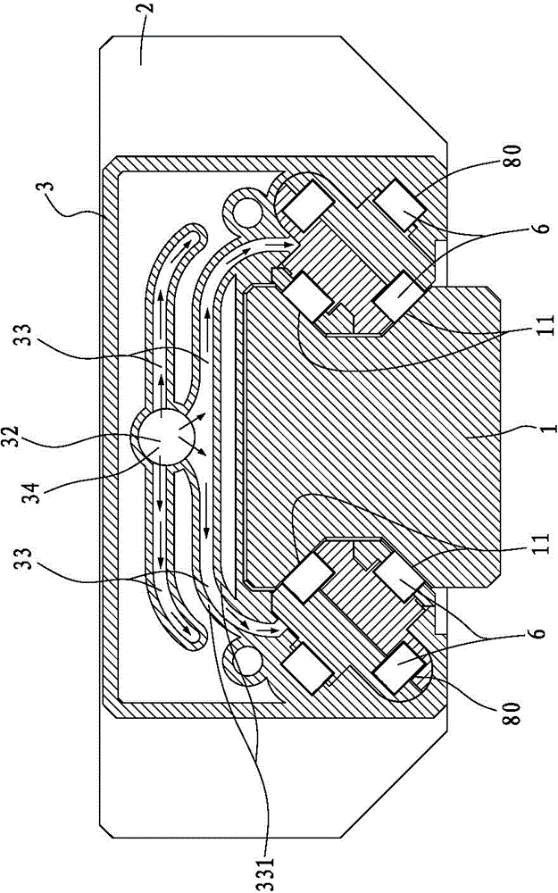
[0057] see Figure 6 and Figure 7 In the present invention, the normal direction of one end of the oil injection passage 32 is closed by the design of the pressure resistance plate 34, so when lubricating oil is injected into the oil injection passage, the lubricating oil will first impact the impact surface 341 of the pressure resistance plate 34 and then Then turn to flow into each of the oil passages 33 respectively, because the pressure resistance plate 34 has absorbed the pressure of the lubricating oil injection, so the pressure of the lubricating oil entering the oil passage 33 has become smaller, and the lubricating oil will not flow from the end cover 3 to the end surface. 23 seeps out, so the present invention prevents lubricating oil from leaking out during the injection process, and also ensures that the lubrication of the linear slide rail is sufficient to prolong its service life.


PUM


Abstract

The invention relates to a linear slide rail having lubricating oil paths. The linear slide rail includes: a rail bar which is provided with a plurality of first rolling surfaces; a slide block, wherein the slide block is sleeved on the rail bar, and is arranged on a second rolling surface opposite to a first rolling surface, the slide block is provided with a plurality of through holes, and the through holes penetrate through two end surfaces of the slide block; and two end covers, wherein the two end covers are covered on the two end surfaces of the slide block respectively, each of the end covers is provided with an oil injection path, a damping board and a plurality of oil paths, the oil injection path penetrates through the end cover, the damping board is arranged at one end of the oil injection path, the shape outline of the damping board is opposite to the inner edge outline of the oil injection path, the damping board is arranged in the normal direction of the oil injection path to make the normal direction of the oil injection path in a shielded form, and damping board arranged end portion of the oil injection path is communicated with all the oil paths, and the normal directions of the oil paths are in an open form.

Description

technical field [0001] The invention relates to a linear transmission assembly, especially a linear sliding rail with a lubricating oil passage. Background technique [0002] see Figure 1 to Figure 3 Shown is the system diagram of the known linear slide rail, the cross-sectional view of the lubricating oil passage of the linear slide rail and the combination diagram of the linear slide rail; The configuration of which is provided with a plurality of first rolling surfaces 11; a slider 2, which is sleeved on the rail 1, and is provided with a second rolling surface 21 opposite to the first rolling surface 11, and the slider The block 2 is further provided with a plurality of through holes 22, and the through holes 22 run through the two end surfaces 23 of the slider 2; Half of the return channel 31, the oil injection channel 32 and a plurality of oil passages 33, the oil injection passage 32 runs through the end cover 3, an oil nozzle 5 is provided at one end of the oil inj...

Claims


Application Information

Patent Timeline
Patent Type & Authority Patents(China)
IPC IPC(8): F16C29/06F16C33/66
Inventor 李家扬
Owner HIWIN TECH
Why Eureka
Eureka Blog
Learn More