Eureka AIR delivers breakthrough ideas for toughest innovation challenges, trusted by R&D personnel around the world.

Sealing ring

Active Publication Date: 2009-01-15
CARL FREUDENBERG KG
View PDF25 Cites 13 Cited by
  • Summary
  • Abstract
  • Description
  • Claims
  • Application Information

AI Technical Summary

Benefits of technology

[0009]It is an object of the present invention to further refine a universal sealing ring of the type mentioned at the outset in such a way that the above-mentioned disadvantages will be overcome, and the sealing ring will exhibit improved performance characteristics for sealing liquid or gaseous media. It is intended that the sealing ring according to the present invention provide reliable sealing action at relatively high pressures and / or when performing dynamic sealing tasks at high relative speeds.

Problems solved by technology

An inherent disadvantage of O-rings is that, during installation or normal use, particularly when performing dynamic sealing tasks in the presence of axial motion of the machine elements to be sealed from one another, they are subject to the risk of twisting / distortion.
This produces high frictional forces in response to the relative motion of the machine elements to be sealed from one another, because the round sealing edges of the sealing rings then flatten considerably, resulting in a large contact surface at the machine elements to be sealed.
Another disadvantage inherent to the manufacturing process is that the O-rings have flash lines which, for the most part, are located on the inside and outside diameters and, thus, precisely on the functional surfaces important to many sealing applications.

Method used


Image

  • Sealing ring
  • Sealing ring
  • Sealing ring

Examples


Embodiment Construction

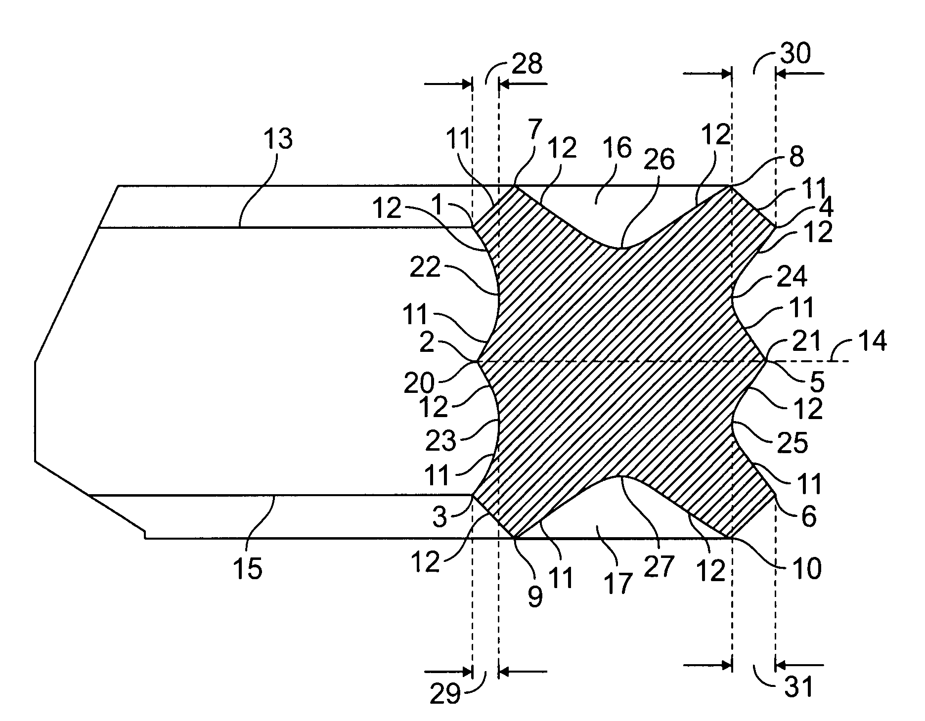
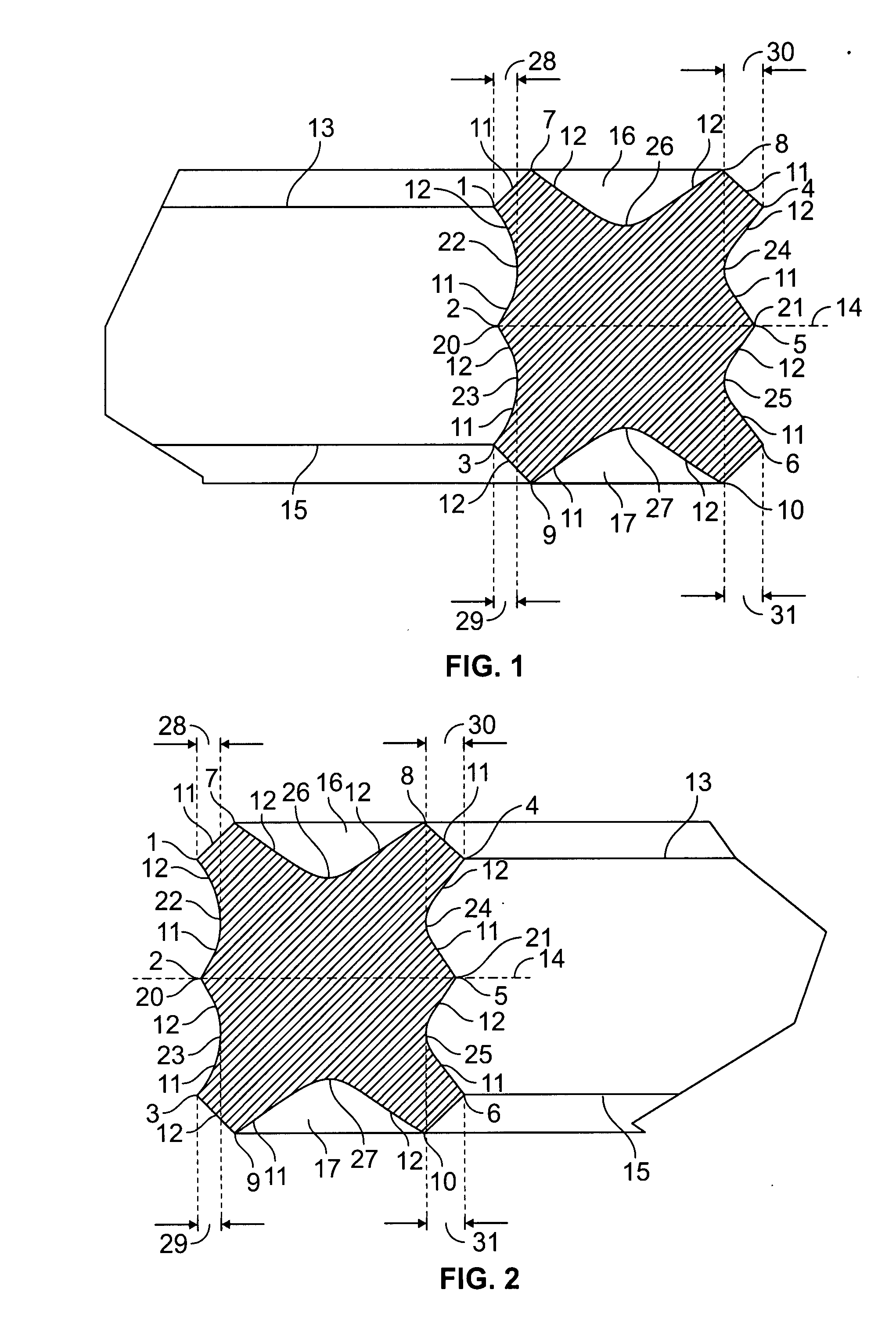
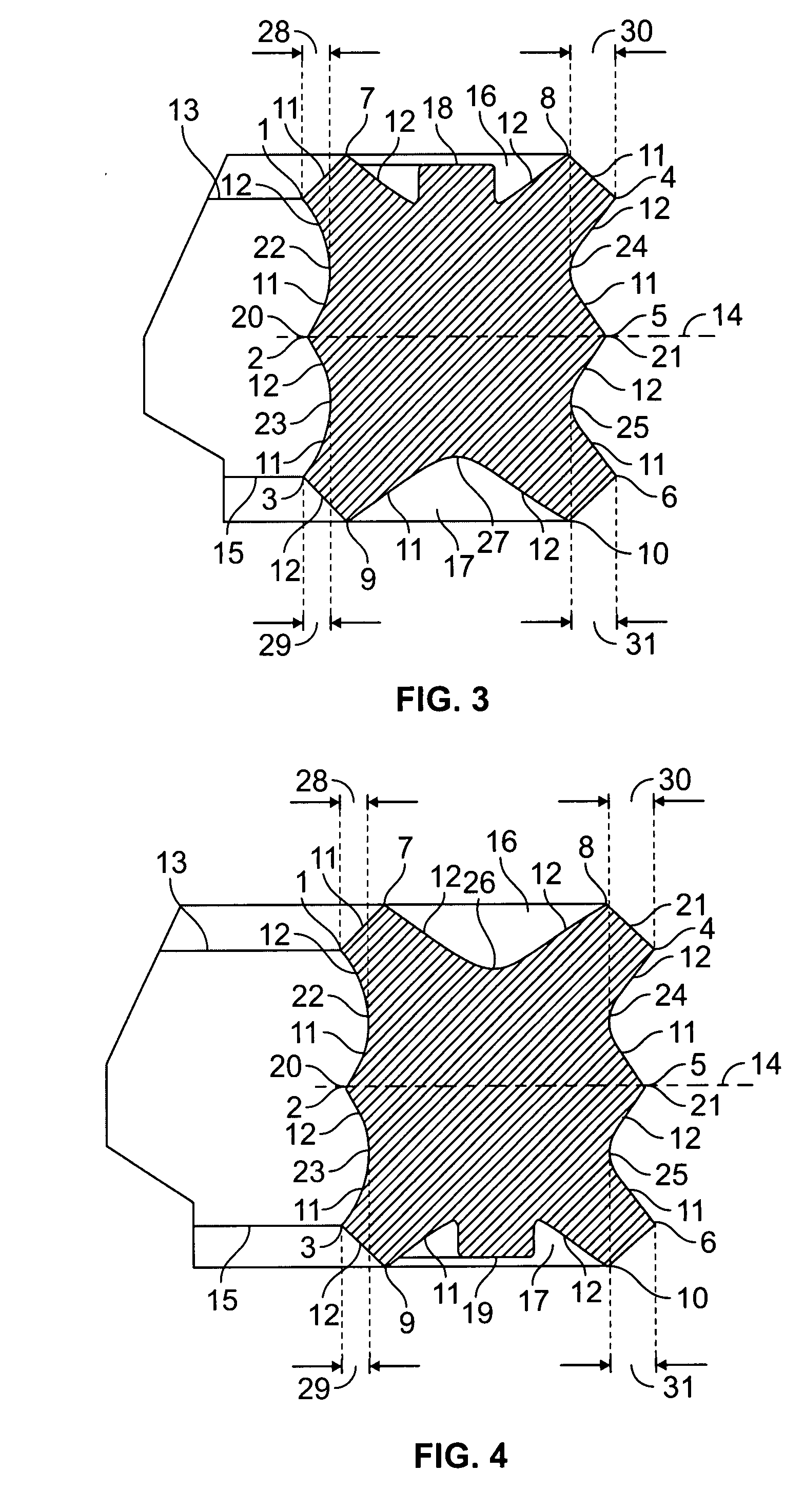
[0044]Ten exemplary embodiments of the sealing ring according to the present invention are illustrated in FIG. 1 through 10.

[0045]Each of the sealing rings has at least eight sealing edges 1 through 8 which are each bounded by mutually intersecting conical surfaces 11, 12.

[0046]The illustrated sealing rings are manufactured using different methods.

[0047]The exemplary embodiments of FIGS. 1, 3, 5, 7 and 9 are manufactured in a mold having an inwardly-engaging mushroom-shaped ejector.

[0048]An exemplary embodiment of a mushroom-shaped ejector is shown in FIG. 11. Transitional regions 24, 25 each have a larger projected annular surface area than transitional regions 22, 23 on the inside diameter of the sealing ring. Thus, the sealing ring remains stuck by its transitional regions 24, 25 to the ejector side and is able to be pushed out of the mold by mushroom-shaped ejector 32. The sum of the projected annular surface areas of the radially outer transitional regions 24, 25 is greater tha...


PUM


Abstract

The present invention provides a sealing ring having at least eight sealing edges. Sealing rings, such as O-ring seals, are generally known. These universal sealing rings can be used for statically or dynamically sealing machine elements. They have the advantage of being suited for a wide variety of possible applications, and of being simple and cost-effective to manufacture.

Description

[0001]This claims the benefit of European Patent Application No. 06 005 968, filed Mar. 23, 2006, and hereby incorporated by reference herein.FIELD OF THE INVENTION[0002]The present invention relates to a sealing ring.BACKGROUND[0003]Sealing rings, such as O-ring seals, are generally known.[0004]These universal sealing rings can be used for statically or dynamically sealing machine elements. They have the advantage of being suited for a wide variety of possible applications, and of being simple and cost-effective to manufacture.[0005]An inherent disadvantage of O-rings is that, during installation or normal use, particularly when performing dynamic sealing tasks in the presence of axial motion of the machine elements to be sealed from one another, they are subject to the risk of twisting / distortion.[0006]Moreover, in order to provide an effective sealing action when performing dynamic sealing tasks, it is necessary for the previously known sealing rings to be vigorously compressed i...

Claims


Application Information

Patent Timeline
IPC IPC(8): F16J15/34
CPCF16J15/025F16J15/061F16J15/3268F16J15/3232F16J15/106
Inventor FIETZ, ROLAND
Owner CARL FREUDENBERG KG
Why Eureka
Eureka Blog
Learn More