Steering devices for vehicles

A control device and vehicle technology, which is applied to the steering control, steering column, steering mechanism and other directions installed on the vehicle, can solve the problems of torque sensor detection accuracy deterioration, bearing life impact, etc., to reduce dumping, save space, reduce The effect of manufacturing costs

Inactive Publication Date: 2015-12-02
JTEKT CORP
View PDF7 Cites 2 Cited by
  • Summary
  • Abstract
  • Description
  • Claims
  • Application Information

AI Technical Summary

Problems solved by technology

The occurrence of dumping will affect the bearing life
In addition, the detection accuracy of the torque sensor will also deteriorate

Method used


Image

  • Steering devices for vehicles
  • Steering devices for vehicles
  • Steering devices for vehicles

Examples


Embodiment Construction

[0020] The preferred embodiments of the present invention will be described with reference to the drawings.

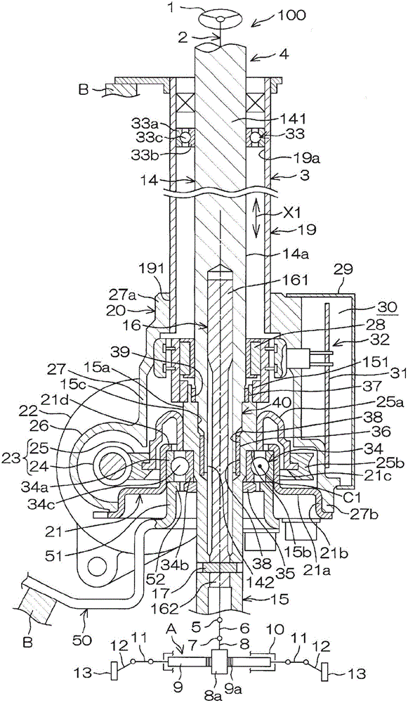
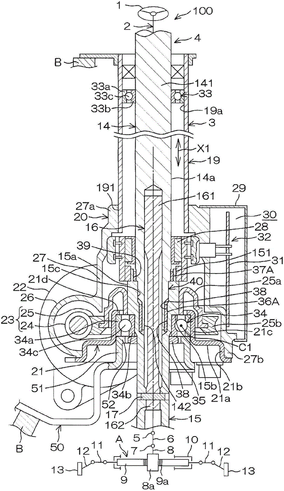
[0021] figure 1 It is a schematic cross-sectional view of an electric power steering system 100 as a vehicle steering system according to an embodiment of the present invention. Reference figure 1 The electric power steering device 100 includes a steering shaft 2 for transmitting the rotation of a steering wheel 1 as a steering member. The steering shaft 2 includes: a column shaft 4, which is rotatably supported by a steering column 3 as a support member fixed to the vehicle body B; an intermediate shaft 6, which is connected to the column shaft 4 via a universal joint 5; and a pinion gear The shaft 8 is connected to the intermediate shaft 6 via a universal joint 7.

[0022] In addition, the electric power steering device 100 includes a steering mechanism A constituted by a rack and pinion mechanism. The rack and pinion mechanism includes: the pinion shaft 8 described abov...


PUM


Abstract

A steering shaft (2) penetrating through a hollow support member (3) includes an upper shaft (14) and a lower shaft (15) which are coaxially connected through a torsion bar (16). A first ball bearing (33) retained by the support member (3) rotatably supports the upper end (141) of the upper shaft. A second ball bearing (34) retained by the support member (3) rotatably supports the lower shaft (15). A first inter-shaft bearing (36; 36A) retained by the lower shaft (15) rotatably supports the lower end (142) of the upper shaft (14). A second inter-shaft bearing (37; 37A) retained by the upper shaft (14) rotatably supports the upper end (151) of the lower shaft (15). The first inter-shaft bearing (36; 36A) includes a portion disposed inward radially of the bearing center (C1) of the second ball bearing (34). The first and second inter-shaft bearings (36, 37; 36A, 37A) are separated from each other in the direction (X1) of the axis of the steering shaft (2).

Description

Technical field [0001] The invention relates to a steering control device for a vehicle. Background technique [0002] Generally, in an electric power steering device, a plurality of ball bearings are used to support the steering shaft. For example, in Patent Document 1, the steering shaft is composed of an upper shaft, an intermediate shaft rotatably connected to the lower end of the upper shaft, and a lower shaft rotatably connected to the intermediate shaft via a torsion bar. [0003] The upper end of the upper shaft is supported by the first ball bearing. The intermediate shaft is supported by the second ball bearing. The lower shaft is supported by the third ball bearing and the fourth ball bearing on both sides of the worm wheel rotating together with the lower shaft. In addition, a sleeve is arranged in a fitting portion where the intermediate shaft and the lower shaft are fitted. [0004] Patent Document 1: Japanese Patent Application Publication No. 2003-341528 [0005] I...

Claims


Application Information

Patent Timeline
Patent Type & Authority Patents(China)
IPC IPC(8): B62D5/04B62D1/16
CPCB62D1/16B62D6/10
Inventor 九郎丸善和
Owner JTEKT CORP
Why Eureka
Try Eureka