Filter structure

A technology of filtering structure and filtering surface, applied in the direction of dispersed particle filtration, dispersed particle separation, chemical instruments and methods, etc., can solve the problems of poor filtering effect, etc. Effect

Inactive Publication Date: 2013-09-04
李乃华
View PDF0 Cites 1 Cited by
  • Summary
  • Abstract
  • Description
  • Claims
  • Application Information

AI Technical Summary

Problems solved by technology

[0004] The purpose of the present invention is to provide a filter structure, which can solve the problems in the above-mentioned background technology, and can overcome the defect of poor filtering effect

Method used


Image

  • Filter structure
  • Filter structure

Examples


specific Embodiment approach

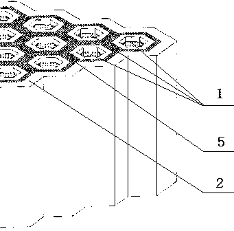
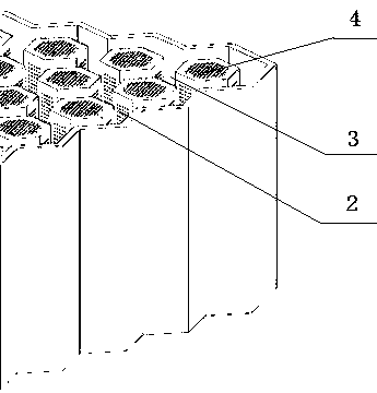
[0012] The specific implementation is as follows: use the filter structure of the present invention to filter the air, blow the air into the cylindrical shape of the air intake unit 1 through the openings of the multiple air intake units 1 provided, and in addition, a part of the air can pass through The filter surface 5 set in the gap 3 enters into the cylindrical shape, and the side filter surface 2 set on the side wall of the air intake unit 1 and the bottom filter surface 4 set at the bottom end of the air intake unit 1 enter into the cylindrical shape to filter the air. filter. Through the opening end of the air intake unit 1 and the gap 3, the intake of air is increased, the filter surfaces on multiple surfaces are set, an air flow direction is designed, the filter area is increased, the filter efficiency is improved, and the filter throughput per unit area increase.


PUM


Abstract

The invention discloses a filter structure, and relates to the field of air filters. The filter structure comprises air inlet units; each air inlet unit is cylindrical; the side wall of the air inlet unit is a side filtering surface; one end of the air inlet unit is open, and a bottom filtering surface is arranged at the other end; the air inlet units are arranged in a tiling manner; a gap is arranged between two adjacent air inlet units; and filtering surfaces are arranged in the intervals close to the open ends of the air inlet units and connect the air inlet units into a whole. The filter structure is designed to have an air flow, so that the filtering area is increased, the filtering efficiency is increased, and the filtering through-put capacity per unit area is increased.

Description

technical field [0001] The invention relates to the field of air filtration, in particular to a filtration structure. Background technique [0002] Air filters are also known as primary air filters or coarse air filters. Air filters are generally made of rayon and fibrous filter media, so they have very good moisture resistance. The general structure of the filter in the prior art is to be provided with a plurality of air inlets, filter surfaces are provided on both side walls of the filter, and other fine dust can be effectively filtered by using the filter surfaces on both sides. Although the filter surfaces on both sides can block fine particles of dust, but through multiple air inlets to increase the air volume, in the case of increased air volume, the filtering effect of this filter structure is very poor, and the filtration efficiency is very low; In terms of production cost, multiple air inlets are added, which increases the cost, but does not improve the filtration...

Claims


Application Information

Patent Timeline
Patent Type & Authority Applications(China)
IPC IPC(8): B01D46/24
Inventor 李乃华
Owner 李乃华
Why Eureka
Try Eureka