A multi-line scanning laser radar device

A technology of laser radar and line scanning, which is applied in the direction of radio wave measurement systems and instruments, can solve the problems of different aberrations, immature development of focal plane arrays, inaccurate target information, etc.

Inactive Publication Date: 2015-12-23
HEFEI INSTITUTES OF PHYSICAL SCIENCE - CHINESE ACAD OF SCI
View PDF4 Cites 18 Cited by
  • Summary
  • Abstract
  • Description
  • Claims
  • Application Information

AI Technical Summary

Problems solved by technology

Although non-scanning imaging lidar has the advantages of simple structure and fast imaging speed, the development of its focal plane array is not mature, especially in China, area array detectors are difficult to obtain, so currently lidar mostly uses scanning imaging working system
[0005] The current laser radar technology is mainly to convert a part of the scattered photoelectric signal into an electrical signal through frequency mixing to display the target signal. During the conversion, there is signal loss and the target information is inaccurate.
In addition, the current imaging method of laser radar for scanning imaging has certain limitations: most of them use non-concentric spherical lenses, and the laser group and its corresponding APD receiving device are placed on the focal plane. The aberrations of the laser group and the laser group on the optical axis are different, resulting in different measurement errors

Method used


Image

  • A multi-line scanning laser radar device
  • A multi-line scanning laser radar device
  • A multi-line scanning laser radar device

Examples


Embodiment Construction

[0059] The present invention will be further described below in conjunction with embodiment.

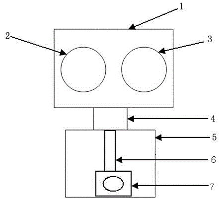
[0060] like figure 1 As shown, a multi-line scanning laser radar device includes a moving part connected by a rotating support 4 and a fixed part 5, and the moving part 1 is provided with a laser emitting optical system 2 and a laser receiving optical system 3 in parallel; The fixed part 5 is provided with a driving motor 7, and the driving motor 7 is fixedly connected to the rotating support 4 through the rotating shaft 6; the laser emitting optical system 2, the laser receiving optical system 3 and the driving motor 7 are respectively connected to the driving control system electrical connect. The drive control system includes a controller, a timing control circuit and a data processing circuit, the output of the controller is respectively connected to the input of the laser emitting optical system 2, the laser receiving optical system 3, and the driving motor 7 through the timing...


PUM


Abstract

The invention provides a multi-line scanning laser radar device, which comprises a moving part and a fixed part which are connected by a rotary support, wherein a laser emitting optical system and a laser receiving optical system are arranged inside the moving part in parallel; a driving motor is arranged inside the fixed part and is fixedly connected with the rotary support through a rotating shaft; and the laser emitting optical system, the laser receiving optical system and the driving motor are electrically connected with a driving control system respectively. The aim of performing multi-line three-dimensional scanning on an imaging target is fulfilled, and the imaging speed and the imaging quality are improved.

Description

technical field [0001] The invention belongs to the technical field of laser radar, and specifically relates to a multi-line scanning laser radar device realized by using a concentric spherical lens group. Background technique [0002] LiDAR is mainly composed of transmitting system, receiving system, signal processing, follow-up control system and display system. Its working principle is as follows: the laser emits laser light, and shoots into the space through the optical modulator, beam controller and optical scanning system. Under the control of the scanning system, the laser beam scans in the space in a specific way. When the laser spot irradiates the target, Scattering occurs, and a part of the photoelectric signal scattered back is detected on the optical detector through the optical receiving system, and then converted into an electrical signal by frequency mixing, and then amplified, information processed, and finally the target signal is displayed. [0003] Imagin...

Claims


Application Information

Patent Timeline
Patent Type & Authority Patents(China)
IPC IPC(8): G01S7/481
Inventor 毛雪松陈向成梅涛
Owner HEFEI INSTITUTES OF PHYSICAL SCIENCE - CHINESE ACAD OF SCI
Why Eureka
Try Eureka