
Rotatable LED down lamp and spotlight

A technology of LED downlights and LED light boards, which is applied to lighting devices, light sources, components of lighting devices, etc., can solve the problems of cumbersome adjustment angle structure, inability to adjust angles, and LED burnout, and achieve simple structure, quick installation, low cost effect

Inactive Publication Date: 2015-05-20
浙江铭光光电科技有限公司
View PDF5 Cites 0 Cited by
  • Summary
  • Abstract
  • Description
  • Claims
  • Application Information

AI Technical Summary

Problems solved by technology

Like all electronic parts, LEDs will generate heat and temperature rise during use or operation. If the heat dissipation problem is ignored, it will cause the LED to burn out early due to high temperature.
Existing LED downlights have the problems of being unable to adjust the angle or having a bulky structure, high cost, and easy damage.

Method used


Image

  • Rotatable LED down lamp and spotlight
  • Rotatable LED down lamp and spotlight
  • Rotatable LED down lamp and spotlight

Examples


Embodiment 1

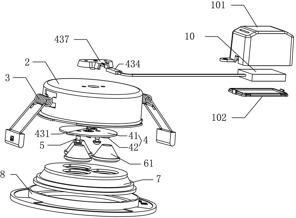
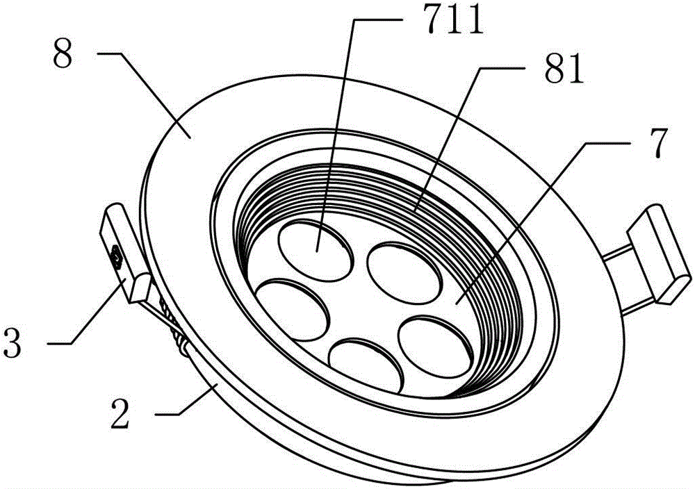
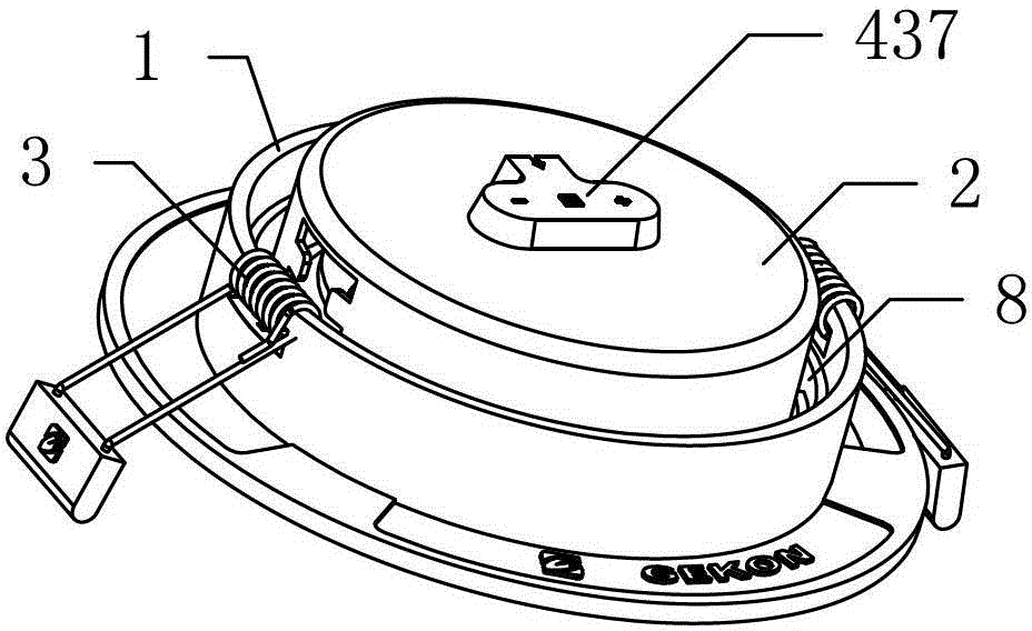
[0034] like Figures 1 to 13 As shown, a rotatable LED downlight includes a cup body 2, an LED lamp board 4, a panel, a light-transmitting component, and a driving power supply. The LED lamp board 4 is fixed in the cup body 2, and the panel is arranged on the cup The mouth of the body 2, the light-transmitting component is arranged in the cup body 2 between the LED light board 4 and the panel, and the driving power is electrically connected to the LED light board 4. Two springs 3 are arranged symmetrically on both sides of the cup body 2 . The LED lamp board 4 is fixed in the cup body 2 by screws 5 . The driving power is located outside the cup body 2, and also includes an outer ring body 1, the panel is arranged in the outer ring body 1, and two locking shafts 84 are arranged symmetrically on both sides of the panel. In this embodiment, the locking shafts 84 It is arranged on both sides of the inner ring body 8 , and the two sides of the inner wall of the outer ring body 1 ...

Embodiment 2

[0042] like Figures 15 to 20 As shown, the difference from Embodiment 1 is that the LED lamp board 4 includes a substrate 41 fixed in the cup body 2 and a number of LED lamp beads 42 arranged on the substrate 41, and the light-transmitting component is a truncated cone. Shape reflective paper ring 62, the panel is provided with a light-transmitting cover 72, the LED light board 4 is ringed at the narrow end of the reflective paper ring 62, and the face cover 72 is ringed at the wide end of the reflective paper ring 62. The reflective paper ring 62 is formed by butt joints of sector pieces 621 , one end of the sector piece 621 is provided with a snap-in piece 622 , and the other end is provided with a snap-in seam 623 for snapping in the snap-in piece 622 . The light distribution adopts a new type of reflective paper, the material can be PET, and the fan-shaped surface is folded, which saves costs and facilitates production operations.


PUM


Abstract

The invention provides a rotatable LED down lamp and spotlight which comprises a cup body, an LED lamp board, a panel, a light transmitting component, a driving power supply and an outer ring. The LED lamp board is fixed in the cup body, the panel is arranged at an opening of the cup body, the light transmitting component is arranged in the cup body and between the LED lamp board and the panel, and the driving power supply is electrically connected with the LED lamp board. The panel is arranged in the outer ring, clamping shafts are arranged on two sides of the panel, and clamping grooves for clamping the clamping shafts are formed in two sides of the inner side wall of the outer ring. The rotatable LED down lamp and spotlight is adjustable in illuminating angle, simple in structure, less prone to being damaged and low in cost.

Description

technical field [0001] The invention relates to the field of lighting fixtures, in particular to a rotatable LED downlight. Background technique [0002] LED lights have broad market prospects due to their advantages of low-voltage power supply, low energy consumption, strong applicability, high stability, short response time, no pollution to the environment, and multi-color luminescence. Like all electronic components, LEDs will generate heat and temperature rise during use or operation. If heat dissipation is ignored, LEDs will burn out early due to high temperatures. The existing LED downlight has the problems of being unable to adjust the angle or having a bulky structure, high cost, and easy damage. Contents of the invention [0003] The technical problem to be solved by the present invention is to provide a rotatable LED downlight with adjustable irradiation angle, simple structure, not easy to damage and low cost. [0004] In order to solve the above-mentioned exi...

Claims


Application Information

Patent Timeline
Patent Type & Authority Patents(China)
IPC IPC(8): F21V17/10F21V19/02F21Y101/02
Inventor 陈继锋
Owner 浙江铭光光电科技有限公司
Learn More