
Gear driving type adjustable LED lamp body mechanism

A technology of LED lamp body and gear drive, which is applied to semiconductor devices of light-emitting elements, damage prevention measures for lighting devices, lighting and heating equipment, etc., which can solve the problem of easy damage of the lamp body, unsatisfactory effect, and inability to adjust the position of the LED lamp body and other issues to achieve the effect of ensuring the service life

Inactive Publication Date: 2017-08-11
付晓明
View PDF0 Cites 5 Cited by
  • Summary
  • Abstract
  • Description
  • Claims
  • Application Information

AI Technical Summary

Problems solved by technology

[0004] The existing LED lamp body is generally directly fixed on the lamp frame, and the lamp frame is fixed, which cannot adjust the position of the LED lamp body. The structure cannot meet the needs. Generally, the LED lamp body arranged in a straight line can only be realized by turning on and off the corresponding LED lamp body step by step. The effect is not ideal, and the lamp body is easy to be damaged if it is switched on and off quickly

Method used


Image

  • Gear driving type adjustable LED lamp body mechanism
  • Gear driving type adjustable LED lamp body mechanism
  • Gear driving type adjustable LED lamp body mechanism

Examples


Embodiment

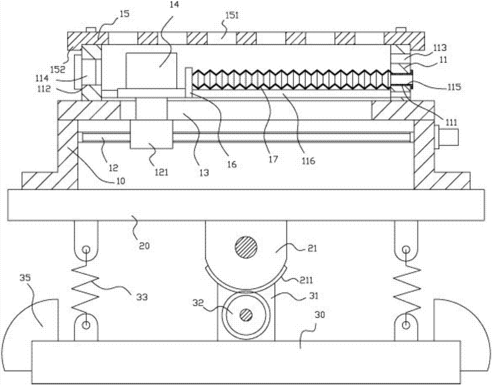
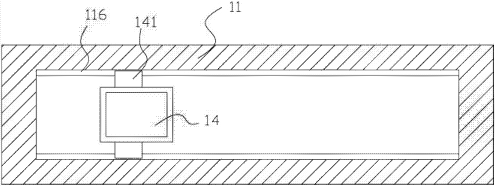
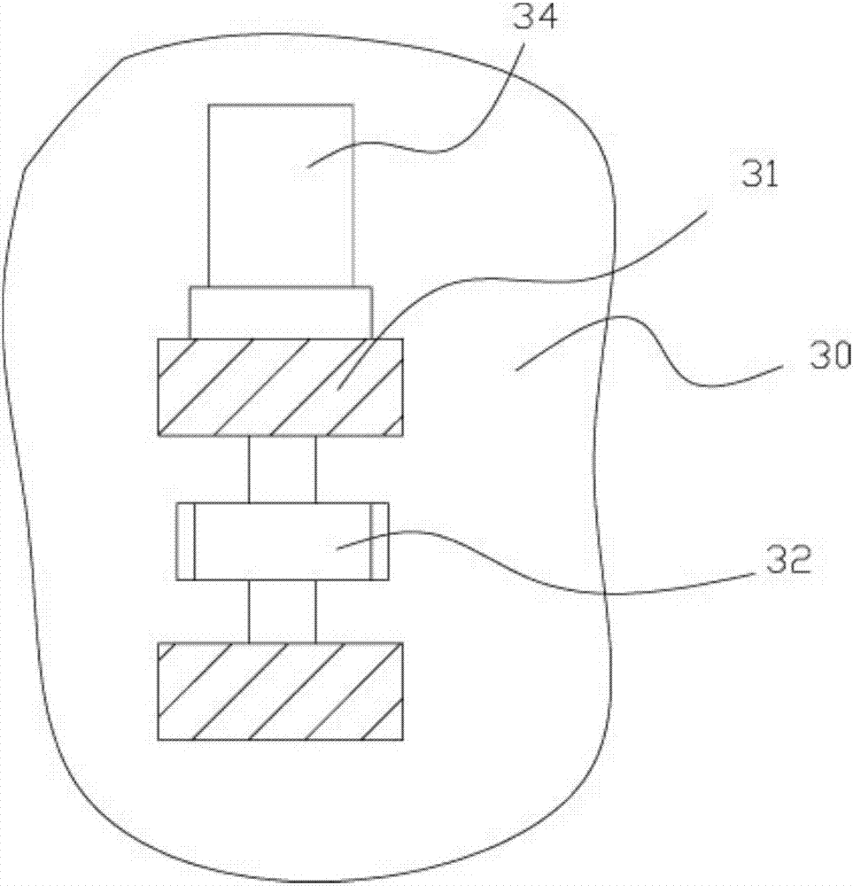
[0024] Example: see Figure 1 to Figure 3 As shown, a gear-driven adjustable LED lamp body mechanism includes a mounting frame 10 and a connecting base plate 20. The mounting frame 10 is fixed on the connecting base plate 20, and a hinge block 21 is fixed in the middle of the bottom surface of the connecting base plate 20. The hinge block 21 is hinged with two connecting blocks 31 on the middle top surface of the lower bottom plate 30 through a connecting shaft. 32 meshes with the arc-shaped tooth portion 211, and a rotation adjustment motor 34 is fixed on the outer wall of one of the connection blocks 31, the output shaft of the rotation adjustment motor 34 is hinged on the two connection blocks 31, and the adjustment drive gear 32 is fixed on the rotation adjustment on the output shaft of the motor 34;

[0025] The upper supporting shell 11 is fixed on the top plate of the mounting frame 10, and the bottom of the top plate of the mounting frame 10 is provided with a transmi...


PUM


Abstract

Disclosed is a gear driving type adjustable LED lamp body mechanism. The gear driving type adjustable LED lamp body mechanism comprises a mounting frame and a connecting base plate. The mounting frame is fixed to the connecting base plate. A hinge block is fixedly arranged in the middle of the bottom surface of the connecting base plate, and hinged with two connecting blocks on the top surface of the middle of a lower base plate through a connecting shaft. An arc-shaped tooth portion is arranged on the bottom surface of the hinge block, and an adjusting driving gear is located between the two connecting blocks, and meshed with the arc-shaped tooth portion. A rotating adjusting motor is fixedly arranged on the outer side wall of one connecting block, and the adjusting driving gear is fixedly arranged on an output shaft of the rotating adjusting motor. By the adoption of the gear driving type adjustable LED lamp body mechanism, an installed LED lamp body can be moved in a linear mode, light transmission is conducted through a plurality of light-transmitting through holes which are formed in an upper cover plate and arranged in a linear mode, the flickering effect is achieved, the LED lamp body does not need to be turned on and off repeatedly, and therefore the service life of the LED lamp body is guaranteed. Meanwhile, the whole mounting frame can be inclined, and therefore the irradiation angle of the gear driving type adjustable LED lamp body mechanism can be adjusted.

Description

[0001] Technical field: [0002] The invention relates to the technical field of LED lamps, in particular to a gear-driven adjustable LED lamp body mechanism. [0003] Background technique: [0004] The existing LED lamp body is generally directly fixed on the lamp frame, and the lamp frame is fixed, which cannot adjust the position of the LED lamp body. The structure cannot meet the needs. Generally, the LED lamp body arranged in a straight line can only be realized by turning on and off the corresponding LED lamp body step by step. The effect is not ideal, and the lamp body is easy to be damaged if it is switched on and off quickly . [0005] Invention content: [0006] The purpose of the present invention is to provide a gear-driven adjustable LED lamp body mechanism for the deficiencies of the prior art, which can move the installed LED lamp body in a straight line and arrange them in a straight line through the upper cover. Multiple light-transmitting holes transmit lig...

Claims


Application Information

Patent Timeline
Patent Type & Authority Applications(China)
IPC IPC(8): F21S8/00F21V14/02F21V15/04F21V17/12F21V19/00F21V21/34F21V23/00F21Y115/10
CPCF21S8/00F21V14/02F21V15/04F21V17/12F21V19/001F21V21/34F21V23/002
Inventor 付晓明
Owner 付晓明
Learn More