Supercharge Your Innovation With Domain-Expert AI Agents!

Film cutting machine

A film cutting machine and film ejecting technology, which is applied in the directions of sending objects, thin material processing, transportation and packaging, etc., can solve the problems of inability to improve the production efficiency of enterprises, low degree of automation, and high labor intensity of workers.

Active Publication Date: 2013-09-25
ZHEJIANG HAIYUE AUTOMATIC MACHINERY
View PDF8 Cites 11 Cited by
  • Summary
  • Abstract
  • Description
  • Claims
  • Application Information

AI Technical Summary

Problems solved by technology

Using this technology to cut, the degree of automation is low, the labor intensity of workers is high, and the production efficiency of the enterprise cannot be improved.

Method used


Image

  • Film cutting machine
  • Film cutting machine

Examples


Embodiment approach 1

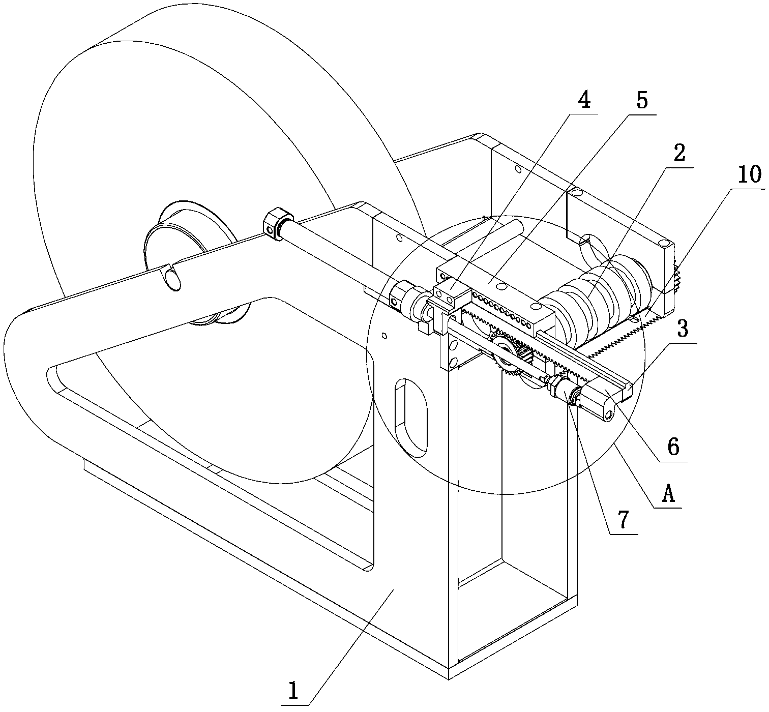
[0022] The driving device adopts an air cylinder or a hydraulic cylinder, the end of the piston rod of the air cylinder or hydraulic cylinder is connected to the rack 3, and a connecting device is provided at the joint, and the connecting device is composed of a floating joint 7 and a rack connecting block 6. , the floating joint 7 is connected to the end of the piston rod, the rack connection block 6 is fixed on the rack 3, and finally the floating joint 7 and the rack connection block 6 are fixed, so that the rack 3 is located in the air cylinder or hydraulic cylinder On one side, the rack 3 does not need to be fixed at the end of the piston rod, which saves space to a certain extent and makes the structure of the whole device more compact.

Embodiment approach 2

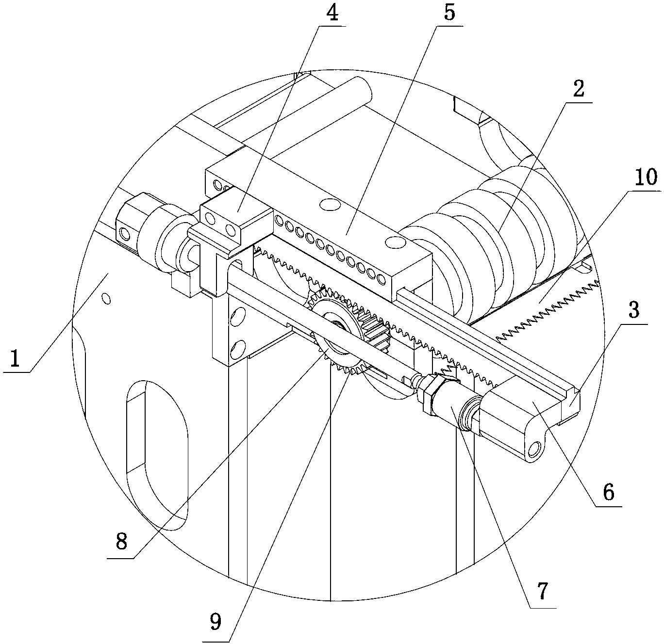
[0024] The driving device adopts a motor, and the output end of the motor is provided with a driving gear, and the driving gear is meshed with the rack 3. During specific implementation, the motor is installed on the support 1 on one side of the one-way bearing 8, and its output end is on the After the driving gear is installed, the driving gear and the gear 9 on the one-way bearing 8 are on the same horizontal plane, and then the rack 3 is installed on the upper part of the driving gear and the gear 9 on the one-way bearing 8, and the driving gear is driven by the motor to reciprocate running, thereby driving the rack 3 to reciprocate, and finally driving the film feeding roller 2 to run.

[0025] The specific embodiment of the drive device mentioned above, as a further improvement, a rack mounting seat 5 is provided above the rack 3, one side of the rack mounting seat 5 is fixed on the bracket 1, and a limit slot, and then set a raised portion on the top of the rack 3 that m...


PUM


Abstract

The invention discloses a film cutting machine which comprises a support. A film feeding roller, a film outlet and a driving device are arranged on the support, the film outlet is positioned on one side of the film feeding roller and provided with a film cutting knife, a one-way bearing is arranged at one end of the film feeding roller, a gear is fixed on the one-way bearing, a rack matched with the gear is arranged on the gear, and the driving device drives the film feeding roller to run by driving the rack. By the aid of the technical scheme, the film cutting machine has the advantages that the rack drives the film feeding roller to run, the film feeding roller also runs once when the rack runs for a length unit as the rack has a length, and the length of a film taken out in every time of rotation of the film feeding roller is consistent.

Description

technical field [0001] The invention relates to a film cutting machine. Background technique [0002] Plastic film or adhesive film needs to be cut from the film roll, and often requires a fixed length during use. In the existing technology, an electric film cutting machine is used to pull the film out of the film roll, and then the length is calculated manually, and then it is cut. Cutting with this technology has a low degree of automation and high labor intensity, which cannot improve the production efficiency of the enterprise. Contents of the invention [0003] The problem to be solved by the present invention is to provide a film cutting machine with simple structure and capable of automatically cutting required lengths. [0004] In order to solve the above-mentioned technical problems, the present invention adopts the following technical solutions: a film cutting machine, including a support, the support is provided with a film feeding roller, a film outlet and a ...

Claims


Application Information

Patent Timeline
Patent Type & Authority Applications(China)
IPC IPC(8): B65H35/06
Inventor 林雁斌张建章倪燮逵周富成费明儿黄亮亮李瑞李征胡勇雄陈义忠张勇根
Owner ZHEJIANG HAIYUE AUTOMATIC MACHINERY
Features
  • R&D
  • Intellectual Property
  • Life Sciences
  • Materials
  • Tech Scout
  • Unparalleled Data Quality
  • Higher Quality Content
  • 60% Fewer Hallucinations
Learn More