Process of repairing a component, a repair tool for a component, and a component

一种修理工具、部件的技术,应用在发动机元件、叶片的支承元件、机器/发动机等方向,能够解决减小应力、延长工作寿命、不去除等问题

Active Publication Date: 2013-09-25
GENERAL ELECTRIC TECH GMBH
View PDF6 Cites 4 Cited by
  • Summary
  • Abstract
  • Description
  • Claims
  • Application Information

AI Technical Summary

Problems solved by technology

Although the gusset shape and consistency help the part meet expected service life, this method does not significantly reduce stress, nor does it remove enough strained material to appreciably extend the feature's operating life

Method used


Image

  • Process of repairing a component, a repair tool for a component, and a component
  • Process of repairing a component, a repair tool for a component, and a component
  • Process of repairing a component, a repair tool for a component, and a component

Examples


Embodiment Construction

[0023] The present invention provides a process for repairing a component, a repair tool for the component, and the component. Embodiments of the present invention result in extended service life of components, reduced or eliminated crack growth, increased turbomachine operability, increased fatigue resistance, or combinations thereof.

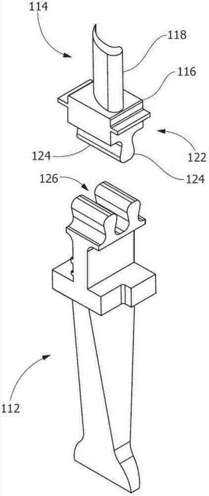
[0024] figure 1 is a perspective view of a portion of a turbine 110 including a rotor wheel 112 and blades 114 according to an embodiment. In general, turbine 110 includes a plurality of rotor wheels 112 , blades 114 , and other turbine components (eg, compressors, shafts, blades, rotor dovetails, and / or other suitable components). Fluid (eg, gas) enters the turbine 110 (eg, through an inlet) and is directed (eg, through the blades) downstream against the blades 114 , and passes through the remaining stages to exert force on the blades 114 , causing the rotor wheel 112 to rotate (eg, around the axis) and vice versa. Turbine 110 is operably ...


PUM


Abstract

A process of repairing a component, a repair tool for a component, and a component are disclosed. The process includes removing material from a region of the component. The removing forms a through-cut in the component, forms a substantially partial-frustoconical geometry in the component, forms a substantially partial-spherical geometry in the component, forms a substantially partial-elliptical geometry in the component, forms a substantially partial-cylindrical geometry in the component, is in a direction substantially perpendicular to a surface of the component, is in a direction substantially inclined with respect to the surface of the component, or a combination thereof. The repair tool includes a securing mechanism and a cutting portion for removing a region. The component includes a region formed by removing material.

Description

technical field [0001] The present invention relates to manufacturing components and processes for forming, repairing or otherwise machining manufactured components. More particularly, the invention relates to components and processes for preparing, forming, repairing or otherwise machining components. Background technique [0002] In general, a turbine rotor assembly includes a rotor wheel to which a plurality of blades are coupled. The blade extends radially outward from a platform that extends between the airfoil portion of the blade and the dovetail portion of the blade. The dovetail portion of the blade has at least one pair of dovetail tangs that couple the rotor blade to complementary dovetail grooves in the outer rim of the rotor wheel. [0003] The dovetail grooves in the outer rim of the rotor wheel are dimensioned to receive the dovetail tangs of the dovetail portion of the blade. These vanes receive cooling air from circumferential grooves intersecting the dov...

Claims


Application Information

Patent Timeline
Patent Type & Authority Applications(China)
IPC IPC(8): F01D25/00
CPCB23P6/005F01D5/005F01D5/3007F05D2230/80Y10T29/49318Y10T29/49718Y10T29/49723Y10T29/49725Y10T29/49726Y10T29/49734Y10T29/49748Y10T29/53961Y10T409/309016
Inventor Y.D.哈蒂瓦拉H.G.哈尔弗森S.库马S.德瓦拉延D.C.拜尔
Owner GENERAL ELECTRIC TECH GMBH
Why Eureka
Try Eureka