
Dynamic monitoring method and system for inquiring maximum competitive position

A dynamic monitoring and competitive technology, applied in special data processing applications, instruments, electrical digital data processing, etc., can solve problems such as inability to solve the problem of optimal location query

Inactive Publication Date: 2017-03-01
SHANGHAI JIAO TONG UNIV
View PDF4 Cites 0 Cited by
  • Summary
  • Abstract
  • Description
  • Claims
  • Application Information

AI Technical Summary

Problems solved by technology

The techniques in these research works do not solve the optimal location query problem, because the closest point query problem is different from the optimal location query problem

Method used


Image

  • Dynamic monitoring method and system for inquiring maximum competitive position
  • Dynamic monitoring method and system for inquiring maximum competitive position

Examples


Embodiment 1

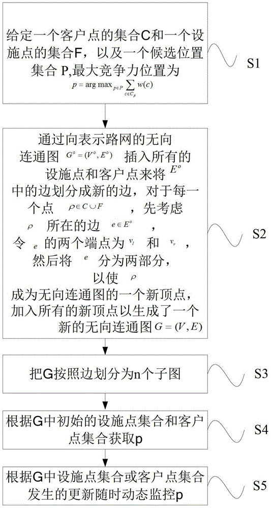
[0135] like figure 1 As shown, the present invention provides a dynamic monitoring method for querying the most competitive position, including steps S1 to S4.

[0136] Step S1, given a set C of customer points, a set F of facility points, and a set P of candidate locations, the maximum competitive location is Where w(c) is the weight of customer point c, if the distance d(c,f) between customer point c and facility point f in the road network is the minimum value of points in c and F, then define f to be c Attractor, c is attracted by f, a(c)=d(c,f) is the attraction distance of c, C p are all customer points that can be attracted by p, namely

[0137] Step S2, through the undirected connected graph G representing the road network o =(V o ,E o ) to insert all facilities f and customers c to E o The edges in are divided into new edges. For each point ρ∈C∪F, first consider the edge e∈E where ρ is located o , let the two endpoints of e be v l and v r , and then divide...

Embodiment 2

[0194] The present invention also provides another dynamic monitoring system for querying the position of maximum competitiveness, including:

[0195] Further, in the above system, the first definition module is used to give a set C of customer points, a set F of facility points, and a set P of candidate positions, and the maximum competitive position is Where w(c) is the weight of customer point c, if the distance d(c,f) between customer point c and facility point f in the road network is the minimum value of points in c and F, then define f to be c Attractor, c is attracted by f, a(c)=d(c,f) is the attraction distance of c, C p are all customer points that can be attracted by p, namely

[0196] Undirected connected graph, used to represent the undirected connected graph G of the road network through directions o =(V o ,E o ) to insert all facilities f and customers c to E o The edges in are divided into new edges. For each point ρ∈C∪F, first consider the edge e∈E whe...


PUM


Abstract

The invention provides a dynamic monitoring method and a dynamic monitoring system for searching optimal competitive location. The dynamic monitoring method includes presetting a customer point set C, a facility point set F and a candidate position set P; inserting all the facility points f and customer points c into an undirected graph shown as the formula Go=(Vo,Eo) for representing a road net to divide edges of the Eo into new edges; to each point p< CUF and on consideration that the edge e where the points p located belongs to Eo, setting two end points of the e as v1 and vr, dividing the e into two parts, namely the part from the v1 to the p and the part from the p to the vr so as to make the p as a new vertex of the undirected graph, adding all the new vertexes to generate a new undirected graph shown as the formula G=(VE) with the condition that V=VoUCUF; dividing the undirected graph G into n sub graphs from G1 to Gn according to edges; acquiring the p according to the initial facility point set F and customer point set C of the undirected graph G; dynamically monitoring the p at any time according to updating of the facility point set F or customer point set C of the undirected graph G; wherein the optimal competitive location is shown as the formula; the value of the n is set according to requirements of users. By the dynamic monitoring method and the dynamic monitoring system, the optimal competitive location can be searched quickly and dynamically.

Description

technical field [0001] The invention relates to a dynamic monitoring and system for inquiring the position of the greatest competitiveness. Background technique [0002] In the past few years, there has been a lot of work on a class of "facility placement problems" in the presence of sets of customer points (see reference 8: Farahani, R.Z., Hekmatfar, M.: Facility Location: Concepts, Models, Algorithms and Case Studies, 1st edn. Physica-Verlag HD (2009), Literature 15: Nickel, S., Puerto, J.: Location Theory: A Unified Approach, 1st edn. Springer (2005)). In the most general case, the problem consists of: (1) a set C of customer points and a set P of facility candidates, and (2) query the locations of k new facilities in P such that a pre-defined optimal condition. This kind of problem has a polynomial time algorithm when k is a constant, and it is an NP-hard problem when k is a general variable (see literature 8 and 15). The existing work mainly studies its approximate al...

Claims


Application Information

Patent Timeline
Patent Type & Authority Patents(China)
IPC IPC(8): G06F17/30
Inventor 姚斌吴亦凡李飞飞肖小奎
Owner SHANGHAI JIAO TONG UNIV
Learn More