Support structure and camera module provided with same

A bracket structure and camera module technology, applied in image communication, camera body, color TV components and other directions, can solve the problems of poor imaging effect of camera module, etc., achieve good imaging effect, ensure filterability, The effect of increasing the space

Inactive Publication Date: 2013-10-09
NANCHANG O FILM OPTICAL ELECTRONICS TECH CO LTD +3
View PDF10 Cites 10 Cited by
  • Summary
  • Abstract
  • Description
  • Claims
  • Application Information

AI Technical Summary

Problems solved by technology

[0004] Based on this, it is necessary to provide a bracket structure and a camera module with the br

Method used


Image

  • Support structure and camera module provided with same
  • Support structure and camera module provided with same

Examples


Embodiment Construction

[0018] The support structure and the camera module with the support structure will be described in detail below in conjunction with specific embodiments and drawings to make it more clear. However, the technical solutions of the bracket structure and the camera module with the bracket structure can be implemented in many different forms, and are not limited to the embodiments described herein. On the contrary, the purpose of providing these embodiments is to make the disclosure of the bracket structure and the camera module with the bracket structure more thorough and comprehensive.

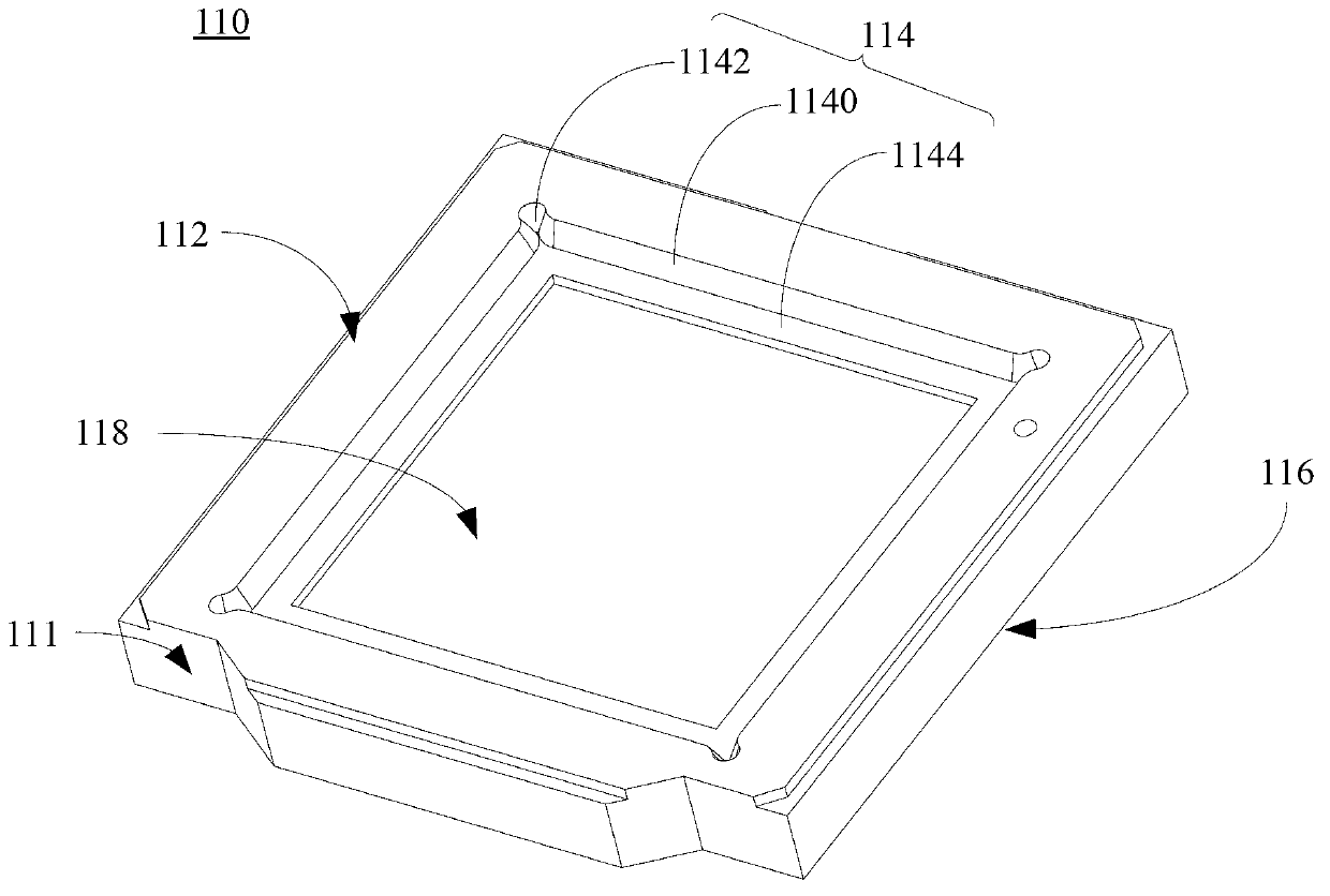
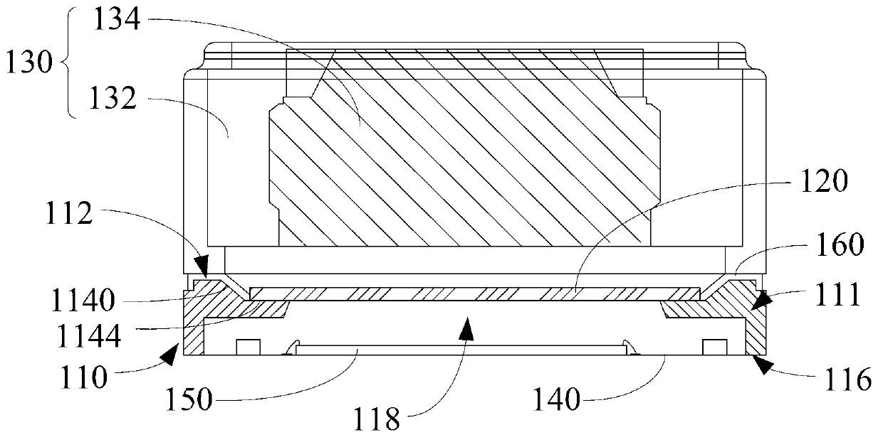
[0019] Such as figure 1 with figure 2 As shown, a bracket structure 110 includes a bracket body 111. The bracket body 111 includes a first surface 112 and a second surface 116 opposite to the first surface 112. The first surface 112 is provided with a concave for placing the filter 120. In the groove 114 , the side wall 1140 of the groove is arranged obliquely relative to the bottom surface 11...


PUM

PropertyMeasurementUnit
Angleaaaaaaaaaa

Abstract

A support structure comprises a support body, wherein the support body comprises a first surface and a second surface which is arranged opposite to the first surface, a groove used for placement of an optical filter is formed in the first surface, the side wall of the groove is arranged obliquely relative to the bottom face of the groove, and the orthographic projection in the direction facing the bottom face of the groove is located outside the bottom face of the groove. Therefore, when the first surface of the support body and a shot drive component are attached in a flush mode through adhesive, due to the fact the side wall of the groove is oblique relative to the bottom face of the groove, according to the hydromechanics, the obliquely-arranged side wall of the groove can provide the guide function for the flow direction of the overflowing adhesive; meanwhile, due to the fact that the side wall of the groove is arranged obliquely, a gap is reserved between the first surface of the support body and the shot drive component to form a containing space, the overflowing part of the adhesive between the first surface and the shot drive component can flow to the containing space along the side wall of the groove and is prevented from overflowing to the surface of the optical filter placed in the groove, the optical filtering performance of the optical filter is ensured, and accordingly the imaging effect of a camera module is good.

Description

technical field [0001] The invention relates to the technical field of camera modules, in particular to a bracket structure and a camera module with the bracket structure. Background technique [0002] With the development of science and technology, more and more portable electronic devices, such as mobile phones, notebook computers, personal digital assistants, etc., have integrated camera modules in order to combine camera functions. The camera module generally installs the lens driving component on the bracket. Because the lens driving component can reflect visible light and invisible light, but the non-visible light will interfere with the imaging of the camera module, it is necessary to install a filter on the side of the bracket where the lens driving component is installed. The non-visible light filter is used to filter out the non-visible light in the light reflected by the lens drive assembly. [0003] At present, the assembly process is completed by bonding the br...

Claims


Application Information

Patent Timeline
IPC IPC(8): G03B17/12G02B7/00G02B7/02H04N5/225G03B30/00
Inventor 齐书于立新
Owner NANCHANG O FILM OPTICAL ELECTRONICS TECH CO LTD
Why Eureka
Try Eureka