Image adjustment device and method

An imaging and imaging lens technology, applied in optics, lenses, instruments, etc., to alleviate ametropia, avoid perspective deformation, and improve user experience

Active Publication Date: 2015-10-21
BEIJING ZHIGU RUI TUO TECH
View PDF6 Cites 0 Cited by
  • Summary
  • Abstract
  • Description
  • Claims
  • Application Information

AI Technical Summary

Problems solved by technology

[0006] The technical problem to be solved by the present invention is to provide an imaging adjustment device and method to solve or reduce the perspective deformation of the object during imaging

Method used


Image

  • Image adjustment device and method
  • Image adjustment device and method
  • Image adjustment device and method

Examples


Embodiment approach

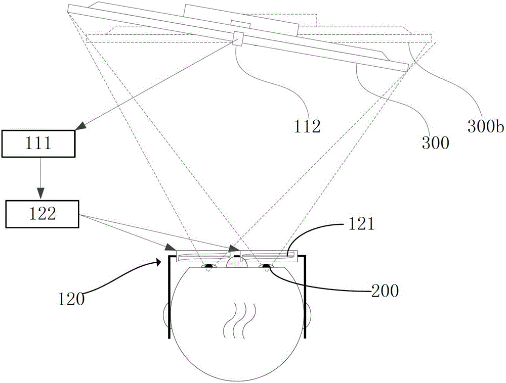
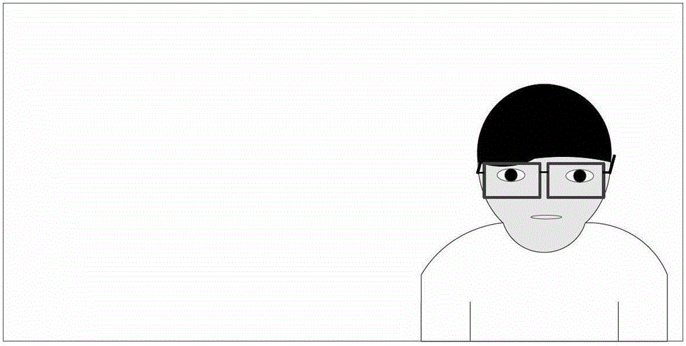
[0165] When the viewer's viewing position is not correct, the offset position and distance of the viewer can be obtained through the depth or image sensor and known screen size, the depth or image sensor position, focal length, pixels and other parameters (for prior art , which will not be repeated in this embodiment), such as Figure 14 Shown is a schematic diagram of a viewer wearing the smart glasses device 610 captured by a depth or image sensor located on the screen 620 in real time, Figure 13 with Figure 14 Medium X L It is the distance from the viewer's left eye 700 to the screen center o, and the distance D from the left eye 700 to the screen L It can be obtained by converting the depth map, or by using an image sensor such as a monocular or binocular camera through known interpupillary distance conversion or triangular geometry calculation.

[0166] According to the position of the viewer (distance X from the viewer's left eye to the screen center o L and the di...


PUM


Abstract

An imaging analysis device (110), an imaging device (120), and an imaging adjustment device and method. The imaging analysis device comprises: an information processing module (111) which is used for receiving position depth information about an imaging lens group (121) and / or an imaging recipient (200) relative to an object (300), obtaining, according to the position depth information, an imaging parameter corresponding to the imaging lens group, and sending the imaging parameter. The imaging device comprises: an imaging lens group which is used for imaging an object, and comprises a plurality of sub-regions (121c) with an imaging characteristic; and a lens adjustment module (122) which is used for receiving an imaging parameter of the imaging lens group output by the imaging analysis device, determining a sub-region corresponding to the imaging parameter and adjusting the imaging characteristic of the sub-region. By imaging the object by means of an imaging lens with a separately adjustable imaging parameter of each sub-region, the occurrence of perspective distortion of the object can be adjusted and corrected, thereby preventing the occurrence of perspective distortion in an image of the object acquired by a user.

Description

technical field [0001] The invention relates to the field of imaging technology, in particular to an imaging adjustment device and method. Background technique [0002] The Galilean telescope can form an upright virtual image 1030a of the observed object 1030 through a convex lens 1010 and a concave lens 1020, and change the angle between the virtual image and the eye, forming a visual effect of zooming in or pushing away the observed object along the optical axis 1040. By adjusting the focal length of the two lenses and the distance between them, the magnification and focus can be changed, such as Figures 17a-17c shown. [0003] Lenses with fixed focal lengths have been widely used in optical devices such as glasses, telescopes, cameras, and microscopes. By combining lenses with different focal lengths and adjusting the distance between the lenses, the lens group can dynamically adjust the focal length. In addition, such as U.S. patent applications with publication number...

Claims


Application Information

Patent Timeline
Patent Type & Authority Patents(China)
IPC IPC(8): G02B13/00G02B3/14G02B26/00G02C7/08
CPCG02B27/0172G02B27/017G02B2027/011G02B2027/0127G02B2027/014G02C7/083G02C7/02G02C7/081G02C11/10
Inventor 杜琳张宏江
Owner BEIJING ZHIGU RUI TUO TECH
Why Eureka
Try Eureka