Method and device for controlling a reluctance electric machine

A control method and technology of reluctance motor, applied in the direction of controlling electromechanical transmission, controlling generator, controlling electromechanical brake, etc., can solve problems such as iron loss

Inactive Publication Date: 2013-10-16
RENAULT SA
View PDF7 Cites 2 Cited by
  • Summary
  • Abstract
  • Description
  • Claims
  • Application Information

AI Technical Summary

Problems solved by technology

Also, for low torques, the shape of the injected current signal is similar to that for high torques, which can create unnecessary iron losses at low torques, and for larger current amplitudes can limit the torque the motor can deliver

Method used


Image

  • Method and device for controlling a reluctance electric machine
  • Method and device for controlling a reluctance electric machine
  • Method and device for controlling a reluctance electric machine

Examples


Embodiment Construction

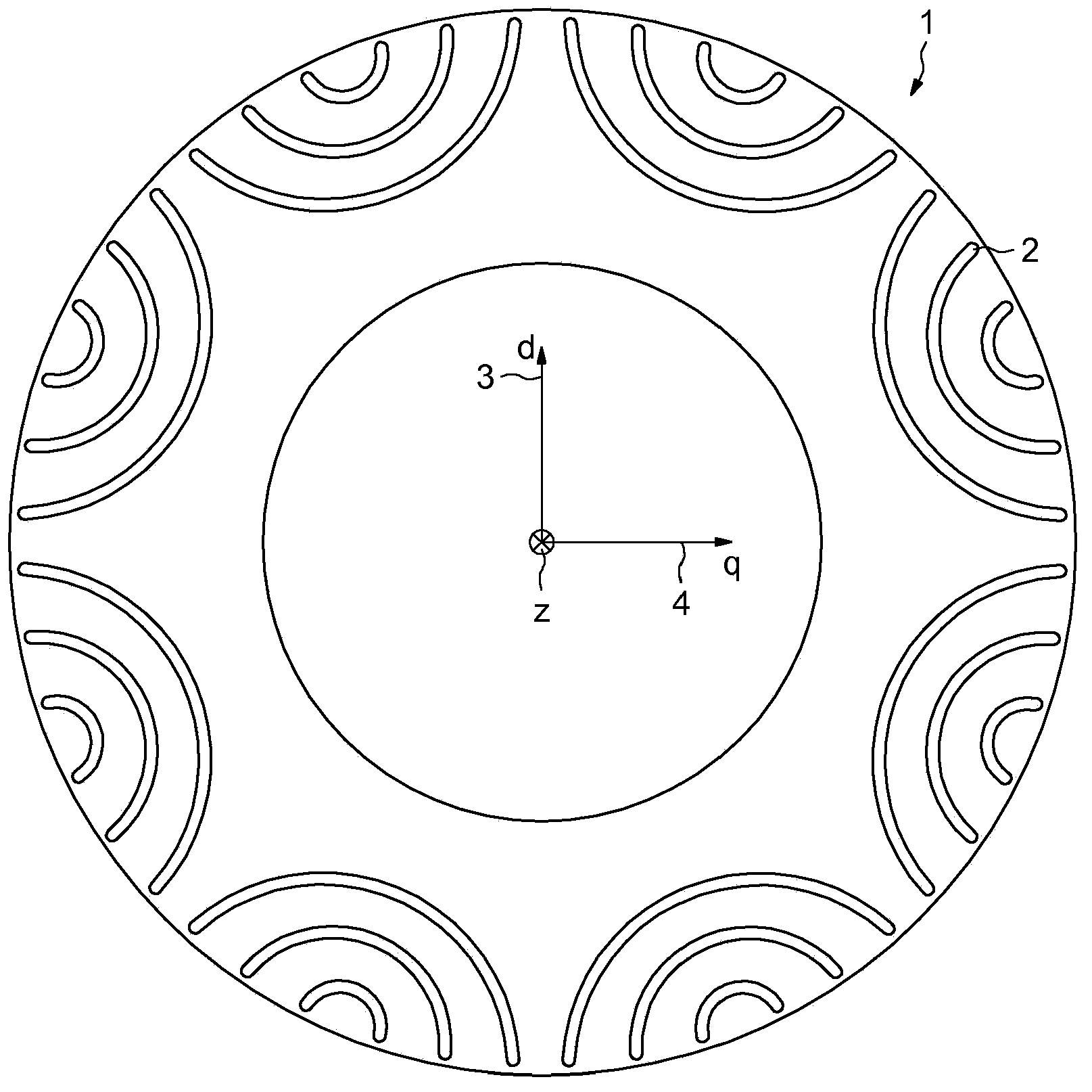
[0043] figure 1 A typical geometry of the rotor of a reluctance machine known as a "sinusoidal synchronous reluctance machine" is shown.

[0044] In this example, the rotor is shown in a plane perpendicular to the axisymmetric axis Z of the rotor.

[0045] The mass of the rotor 1 made of ferromagnetic material is indented by a notch 2 defined by a curved surface portion of a generatrix parallel to the axis z. In the example shown, the contour of the recess 2 is defined by a cylindrical portion of the shaft centered outside the outer circumference of the rotor 1 .

[0046]The end of the notch 2 is close to but not engaged with the outer circumference of the rotor 1 . The notches 2 delimit a smaller rectangular direction along which the orientation of the magnetic field induced inside the rotor 1 tends to be. Such a minimum reluctance axis is for example given by figure 1 Axis 3 or Axis D identification. exist figure 1 Also shown in is an axis q marked 4 perpendicular to b...


PUM


Abstract

In a method of controlling a reluctance polyphase electric machine (36), in particular an automobile motor, the currents injected into each coil of the stator of the machine (36) are deduced by a transformation of a pair (Id, Iq) of excitation currents (Id) and of armature current (Iq) defined in a reference frame (d, q) rotating with the rotor of the machine, such that: - the excitation current (Id) is composed of a fundamental sinusoidal signal, to which are added successively other odd harmonics of increasing order when the torque setpoint of the machine increases, - the armature current (Iq) is a signal proportional to the estimated or measured electromotive force of the machine.

Description

technical field [0001] The subject of the invention is a method for controlling a motor known as a synchronous reluctance motor, and a motor suitable for being able to be controlled according to this method. Background technique [0002] A synchronous reluctance machine comprises a series of stator windings defining the poles of the machine and a rotor which has been made of ferromagnetic material eg with a series of notches to make it easier to build up a magnetic field inside the rotor in certain specific directions. [0003] Furthermore, the rotor can consist of a layered structure in order to limit the current flow within the rotor. [0004] Such motors are often less expensive to produce than motors whose rotors include windings or permanent magnets. For a given current strength, the maximum torque that can be achieved depends inter alia on the control method. [0005] Specifically, the mechanical power produced by an electric motor is proportional to the current inje...

Claims


Application Information

Patent Timeline
Patent Type & Authority Applications(China)
IPC IPC(8): H02P6/08H02P21/00H02P25/08
CPCH02P21/0035H02P25/08H02P6/08H02P25/0925H02P6/10H02P21/0003
Inventor S·德沙尔纳伊斯
Owner RENAULT SA
Why Eureka
Try Eureka