Drive circuit and physical quantity measuring device

a technology of physical quantity and drive circuit, which is applied in the direction of generator/motor, mechanical vibration separation, instruments, etc., can solve problems such as unrealistic, and achieve the effect of stable measuremen

Inactive Publication Date: 2013-07-16
SEIKO EPSON CORP
View PDF7 Cites 3 Cited by
  • Summary
  • Abstract
  • Description
  • Claims
  • Application Information

AI Technical Summary

Benefits of technology

[0010]According to this aspect of the invention, by controlling the amplitude of the drive signal based on the comparative voltage, it is possible to keep the amplitude of the excitation current of the vibrator constant. Firstly, since the first resistor included in the current-voltage conversion circuit and the second resistor included in the comparative voltage supply circuit for supplying the comparative voltage are made of the same material, the rate of the variation in the resistance value due to the temperature is the same. Therefore, the variation in the excitation current in accordance with the temperature variation can be prevented.
[0012]Further, the drive circuit of the comparative example described later has the resistor corresponding to the second resistor as, for example, a low-pass filter of the compensation circuit. However, the drive circuit of the aspect of the invention does not require such a compensation circuit, and therefore the design can be simplified, and the circuit scale is also reduced. Further, the capacitance of the capacitor of the low-pass filter provided to the drive circuit of the comparative example has the variation due to the manufacturing variation although the temperature variation is small. As a result, the variation in the capacitance of the capacitor affects the excitation current, and therefore, the difference in the excitation current occurs between the products including the drive circuit even if the temperature condition is the same. The drive circuit according to the aspect of the invention can keep the amplitude of the excitation current of the vibrator constant without causing such a problem.
[0013]Further, the gain of the drive circuit of the comparative example has a frequency dependency, and the excitation current tends to increase if, for example, the vibrational frequency is raised. However, in the drive circuit according to the aspect of the invention, the gain does not have the frequency dependency, and the amplitude of the excitation current of the vibrator can be kept constant.
[0016]According to this configuration, by disposing the first resistor and the second resistor in the same resistor area in the layout, it is possible to eliminate the local resistance variation to thereby keep the amplitude of the excitation current constant eventually. On this occasion, since the first resistor and the second resistor are disposed in an array fashion, the way of arrangement is the same, which makes it difficult to cause the variation in the resistance value due to the shape. Therefore, it is possible to align the temperature characteristics between the first resistor and the second resistor.
[0022]According to this configuration, the current-voltage conversion circuit including the first resistor and the comparison control circuit including the second resistor are connected to the common ground potential to thereby prevent the difference in the temperature characteristics between the both resistors from occurring, and thus, the amplitude of the excitation current can be kept constant. For example, the resistance values of the first resistor and the second resistor are optimized under a certain condition (e.g., a “TYP” condition (typical condition)) in the design process. On this occasion, by connecting them to the common ground potential, it is possible to reduce the variation in the amplitude of the excitation current due to, for example, the temperature variation as much as possible to thereby prevent the amplitude from reaching the limit value.
[0024]According to the aspect of the invention, it is possible to provide a physical quantity measuring device capable of performing stable measurement by including the drive circuit for keeping the amplitude of the excitation current of the vibrator constant irrespective not only of the temperature variation but also of the manufacturing variation and the variation in frequency.

Problems solved by technology

However, since the circuit design constraints are severe, it is not realistic.

Method used


Image

  • Drive circuit and physical quantity measuring device
  • Drive circuit and physical quantity measuring device
  • Drive circuit and physical quantity measuring device

Examples


first embodiment

1. First Embodiment

[0034]A first embodiment of the invention will be explained with reference to FIGS. 1, 2, 3A through 3C, and 4A through 4C. Further, FIGS. 6 and 7 are also referred to in the explanation of a comparative example.

1.1. Configuration of Drive Circuit of Present Embodiment

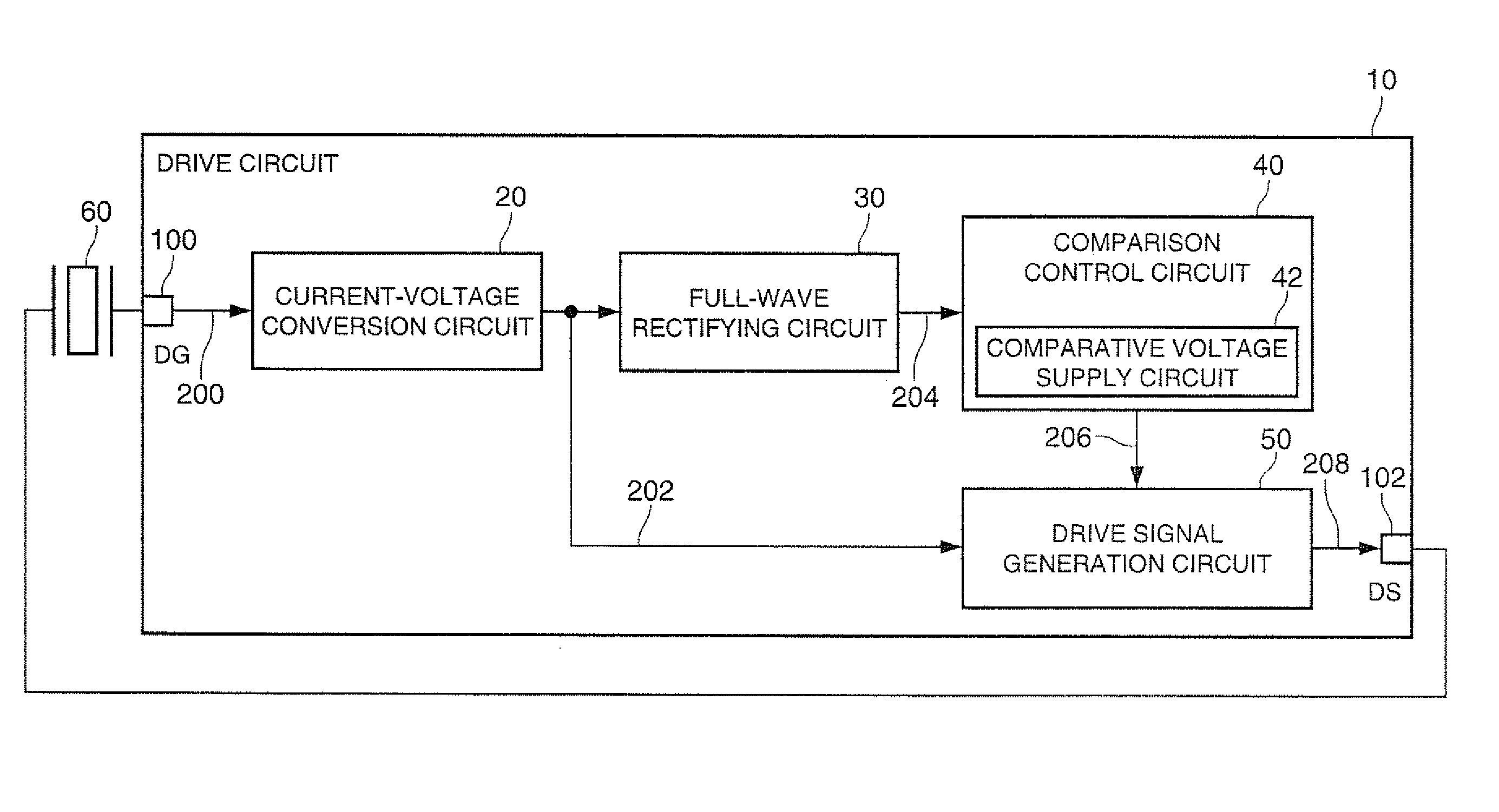
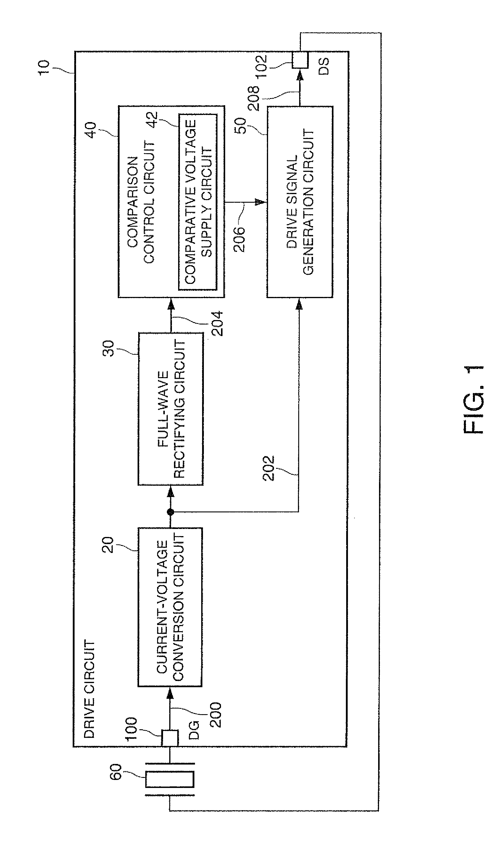
[0035]FIG. 1 is a block diagram of a drive circuit 10 according to the present embodiment. The drive circuit 10 includes a current-voltage conversion circuit 20, a full-wave rectifying circuit 30, a comparison control circuit 40, and a drive signal generation circuit 50.

[0036]The current-voltage conversion circuit 20 converts an excitation current 200 from a vibrator 60 into a voltage to thereby output an output voltage 202. The amplitude of the output voltage 202 is proportional to the amplitude of the excitation current 200.

[0037]The full-wave rectifying circuit 30 performs the full-wave rectification on the output voltage 202 from the current-voltage conversion circuit 20 to thereby obtain a rough...

application example

2. Application Example

[0095]An application example of the drive circuit according to the invention will be explained with reference to FIG. 5. The same constituents as those shown in FIGS. 1, 2, 3A through 3C, and 4A through 4C are provided with the same reference numerals, and the explanation therefor will be omitted.

2.1. Physical Quantity Measuring Device

[0096]FIG. 5 is a diagram showing an example of the physical quantity measuring device 1. The physical quantity measuring device 1 includes the drive circuit 10, a detection circuit 90, the vibrator 60, and a vibrator 70. The detection circuit 90 receives measurement signals 290, 292 as, for example, differential signals from a detection section provided to the vibrator 70. The measurement signals are proportional to the excitation current of the vibrator 60. Then, the detection circuit 90 receives necessary information from the drive circuit 10 as an internal signal 294, then performs a predetermined calculation, and then outputs...


PUM


Abstract

In order for keeping the amplitude of the excitation current of a vibrator constant irrespective not only of the temperature variation but also of the manufacturing variation and the variation in frequency, a comparison control circuit for controlling the amplitude of the drive signal for exciting the vibrator includes a comparative voltage supply circuit for supplying the comparative voltage, and the comparative voltage supply circuit generates the comparative voltage with a constant current source and a second resistor made of a material the same as a material of a first resistor included in a current-voltage conversion circuit.

Description

[0001]The entire disclosure of Japanese Patent Application No. 2010-196933, filed Sep. 2, 2010 is expressly incorporated by reference herein.BACKGROUND[0002]1. Technical Field[0003]The present invention relates to a drive circuit, a physical quantity measuring device, and so on.[0004]2. Related Art[0005]In general, a physical quantity measuring device using a vibrator outputs a measurement signal proportional to the excitation current of the vibrator. In order for stable measurement, there is required a drive circuit or the like for keeping the amplitude of the excitation current constant irrespective of the temperature variation in the measurement environment. In JP-A-2008-261844 (Document 1) there is disclosed an invention of using an element identical to the resistor element of the detection circuit in the drive circuit to thereby cancel out the temperature variation between the excitation current and the detection current, thus stabilizing the output of the measurement signal.[0...

Claims


Application Information

Patent Timeline
Patent Type & Authority Patents(United States)
IPC IPC(8): H01L41/08
CPCB06B1/0207G01C19/5776H02P31/00H01L41/042G01D3/036H10N30/802
Inventor YAMAGUCHI, MASAYUKI
Owner SEIKO EPSON CORP
Why Eureka
Try Eureka