
Device for melting, storing, and feeding metal material from bar-shaped metal material intended for injection apparatus for molding metal product

a metal material and injection apparatus technology, applied in the direction of manufacturing converters, manufacturing tools,foundry moulding apparatus, etc., can solve the problems of large furnace body size, poor molding efficiency, long time, etc., to improve the melting efficiency of bar-shaped metal materials, reduce startup time, and stabilize the temperature of molten metal materials

Inactive Publication Date: 2009-07-16
NISSEI PLASTIC IND CO LTD
View PDF3 Cites 4 Cited by
  • Summary
  • Abstract
  • Description
  • Claims
  • Application Information

AI Technical Summary

Benefits of technology

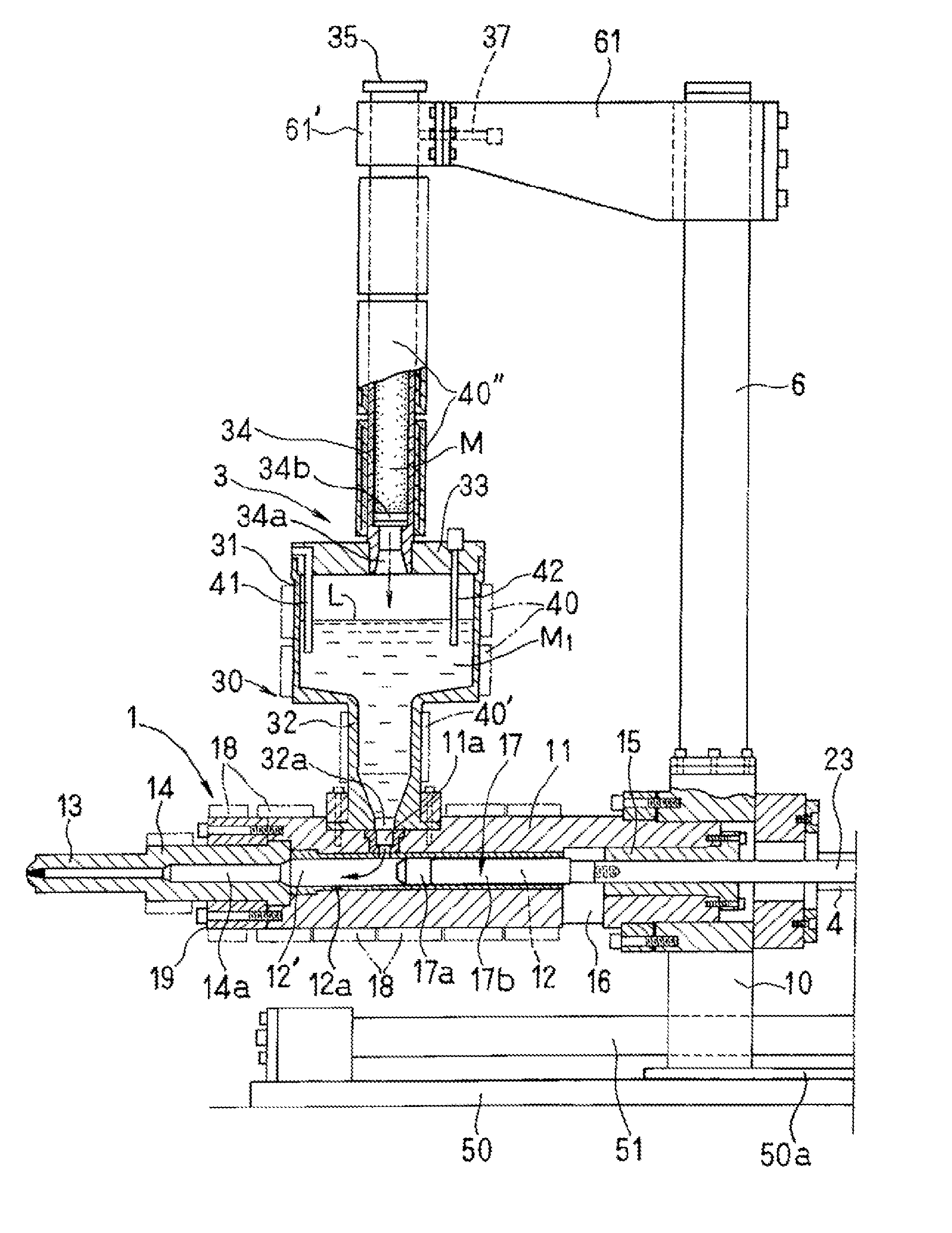
[0011]The present invention has been achieved in order to solve the foregoing problems that are associated with the melting and storing of metal materials from bar-shaped metal materials in a melting furnace and the melting and storing of metal materials from bar-shaped metal materials by using a melting barrel. It is thus an object of the invention to provide a new device for melting, storing, and feeding metal materials from bar-shaped metal materials intended for an injection apparatus for molding a metal product, by which molten metal material is fed into an injection cylinder for each single shot of injection. This device shall use a barrel to melt the bar-shaped metal materials and a tank-and-barrel unit to store the molten metal material so that: it provides high melting efficiency even with a small size capable of installation on an injection cylinder; it can store a large amount of molten metal material corresponding to molding cycles even with the compact configuration; and it can preclude temperature variations of the molten metal material in the storage unit, and feed the injection cylinder with the molten metal material that is adjusted to a set temperature.
[0017]According to the foregoing configuration, the melting of the bar-shaped metal material and the storing of the molten metal material are performed in the melting barrels and the storage unit separately, so that the storage unit is not involved in the melting of the bar-shaped metal material. This precludes the loading-based temperature variations of the molten metal material, which occur in the case of immersion melting in a furnace, thereby stabilizing the temperature of the molten metal material. The molten metal material can be stored in the storage unit which is composed of the tank and the barrel arranged under and in communication with the bottom center of the tank. This makes it possible to store and feed a large amount of molten metal material corresponding to the molding cycles, despite the use of the melting barrels for melting the metal material.
[0018]The more than one melting barrel is vertically arranged in parallel on the lid member of the upper storage tank which constitutes the device for melting, storing, and feeding, so that their bottom openings face the inside of the storage tank. This allows the molten metal material in the melting barrels to be let out and supplied into the storage tank below by gravitation with reliability all the time. The two melting barrels can also perform the melting operation simultaneously for reduced startup time. For alternate operations, either one of the melting barrels can make the melting operation while the other a preheating operation on standby. This improves the melting efficiency of the bar-shaped metal material, and stabilizes the feeding to the injection cylinder when combined with the increased amount of storage.
[0019]The tank and the barrel perpendicularly arranged under and in communication with the bottom center of the tank function as a material temperature control barrel for the molten metal material stored. The molten metal material flowing down from the storage tank into the barrel is then evened to the set temperature while residing in the control barrel. This makes it possible to feed the injection cylinder with the molten metal material of constant temperature by one shot for stable molding. Since the lid member of the storage tank has the swing door parts, these swing door parts can be opened to remove oxides and other impurities floating on the surface of the molten metal easily out of the tank by using cleaning tools.
[0020]Since the storage tank is not involved in the melting of the bar-shaped metal material, the storage unit composed of the tank and the barrel has only to have a capacity sufficient to store molten metal material as much as the more than one melting barrel produces at a time. The height of the storage tank therefore need not be determined to cover the length of the bar-shaped metal material. Besides, the material temperature control barrel has only to have a storage capacity capable of material temperature control corresponding to the molding cycles. This allows a low-height compact configuration which facilitates installation on the injection cylinder.

Problems solved by technology

In other words, the device for melting and storing a metal material using the melting furnace requires a long time for molding startup, with the problem of accordingly poor efficiency of the molding operation.
This inevitably makes the furnace body large in size and heavy in weight, producing the problem that the melting furnace can hardly be adopted for the device for melting and storing a metal material, to be installed on the injection cylinder.
In the apparatuses where the molten metal material is stored in the storage unit outside the injection heating cylinder and is measured out for each single shot by retreating the injection plunger, the storage capacity is limited to that of the insulated storage barrel since the injection heating cylinder itself is not available for storing the metal material.
The number of melting barrels that can be installed on the insulated storage barrel is also limited to one.
Consequently, in terms of the relationship between the melting speed of the metal material and the molding cycles, it is sometimes difficult to melt and feed a sufficient amount of molten metal material corresponding to the molding cycles depending on the weight of metal products to be molded.
This, however, makes the molten metal material to reside longer in the insulated storage barrel, so that temperature differences can occur easily from molten metal material that is newly supplied from the melting barrel.
This is prevented by raising the temperature setting of the insulated storage barrel, which entails the problem of an inevitable increase in the thermal energy consumption.

Method used


Image

  • Device for melting, storing, and feeding metal material from bar-shaped metal material intended for injection apparatus for molding metal product
  • Device for melting, storing, and feeding metal material from bar-shaped metal material intended for injection apparatus for molding metal product
  • Device for melting, storing, and feeding metal material from bar-shaped metal material intended for injection apparatus for molding metal product

Examples


Embodiment Construction

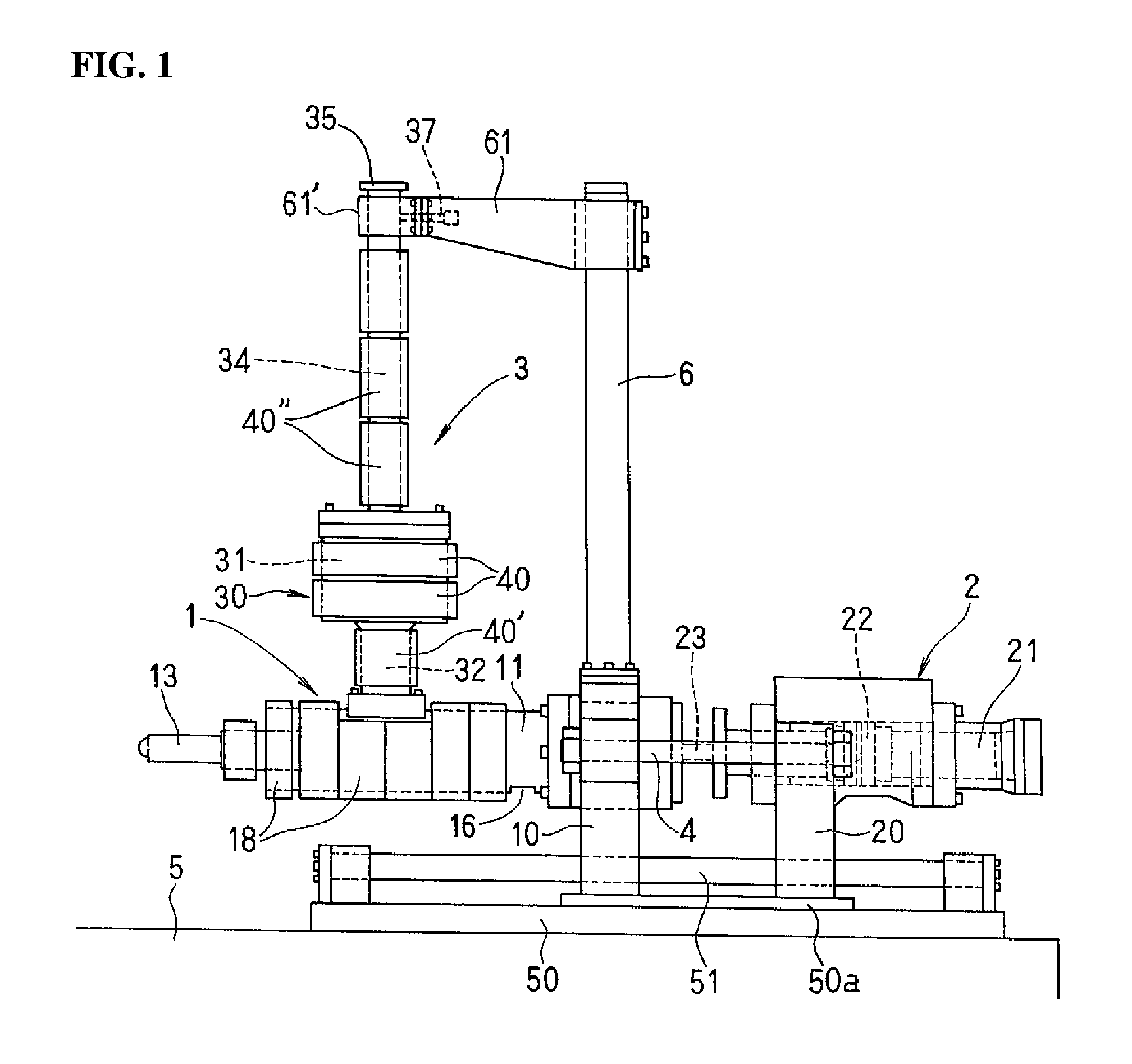
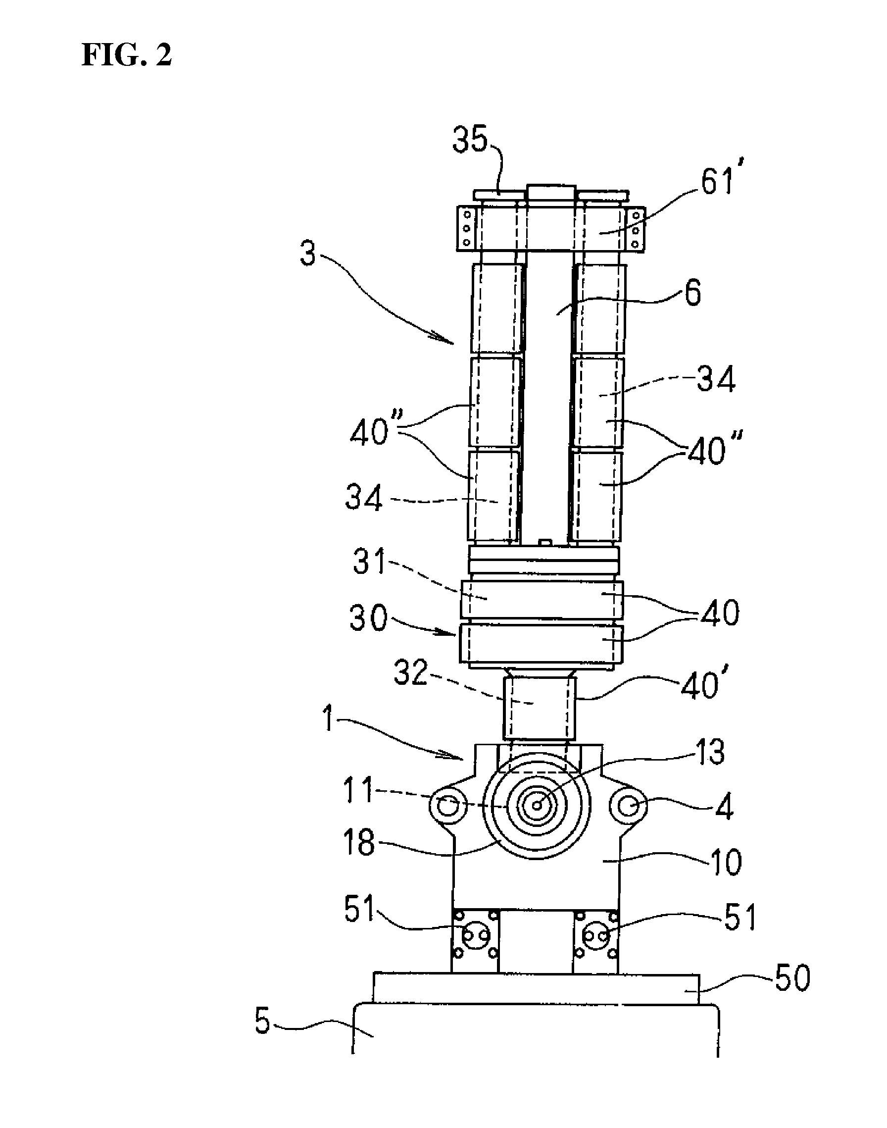
[0026]In the accompanying drawings, the reference numeral 1 designates an injection cylinder, and 2 an injection drive unit which is placed at a distance from the rear end of the injection cylinder 1. The two units are coupled with rods 4 on both sides, and are movably arranged on a base 5. The reference numeral 3 designates a device for melting, storing, and feeding a metal material, which is arranged on a cylinder body 11 of the injection cylinder 1 so as to communicate with the inside of the same.

[0027]The injection cylinder 1 is horizontally installed with the rear end of the cylinder body 11 inserted and fixed to a holding plate 10 on the base 5. The holding plate 10 is pierced with a pair of right and left support shafts 51 arranged in parallel on a seat plate 50 of the base 5, and is fixed at its bottom to a slide plate 50a on the seat plate 50 so that it can reciprocate freely with the cylinder body 11. A support column 6 intended for the device 3 for melting, storing, and f...


PUM

PropertyMeasurementUnit
Fractionaaaaaaaaaa
Fractionaaaaaaaaaa
Temperatureaaaaaaaaaa

Abstract

A device for melting, storing, and feeding a metal material is provided which can store a large amount of molten metal material corresponding to molding cycles with a compact configuration, using barrels to melt bar-shaped metal materials and a tank-and-barrel storage unit to store the molten metal material. The storage unit for the molten metal material is composed of an upper storage tank and a lower material temperature control barrel having a smaller diameter, the barrel being perpendicularly arranged under and in communication with the bottom center of the tank. The melting barrels for bar-shaped metal materials are made of barrel bodies having an inside diameter and a length appropriate to accommodate the bar-shaped metal materials. A more than one melting barrel is vertically arranged in parallel on a lid member of the storage tank, with their bottom openings facing the inside of the storage tank.

Description

BACKGROUND OF THE INVENTION[0001]1. Field of the Invention[0002]The present invention relates to a device for melting, storing and feeding a metal material from a bar-shaped metal material intended for an injection apparatus for molding a metal product, in which bar-shaped metal materials such as magnesium and aluminum are melted and injected into a mold.[0003]2. Description of the Related Art[0004]Among conventional injection apparatuses for molding a metal product is one in which a melting furnace is installed on an injection cylinder having a plunger inside (Japanese Patent Application Laid-Open No. 2004-291032). A solid material is melted and stored in the melting furnace, and the plunger is retreated to create a material measuring chamber in the front part of the cylinder, into which the molten material is fed from the melting furnace and measured (accumulated) for a single shot of injection. The plunger is then advanced to inject the measured material into a mold from a nozzle...

Claims


Application Information

Patent Timeline
IPC IPC(8): B22C5/14
CPCB22D17/30B22D17/28B22D17/04B22D17/32C22C23/00
Inventor MINAMIMURA, MASAAKITAKEUCHI, YASUHIKOKODA, TOSHIYASUMIYAGAWA, MAMORUUWADAIRA, IKUOKAWANO, TAKU
Owner NISSEI PLASTIC IND CO LTD
Learn More