Film Forming Apparatus, Evaporating Jig, and Measurement Method

a film forming and evaporation jig technology, applied in the direction of specific gravity measurement, instruments, mechanical means, etc., can solve the problems of contamination even on a molecular basis, low use efficiency of organic el material, poor light emission efficiency and short life, etc., to improve the use efficiency and accurately control the concentration (evaporation rate) of organic el raw material

Inactive Publication Date: 2009-04-02
TOHOKU UNIV +1
View PDF3 Cites 39 Cited by
  • Summary
  • Abstract
  • Description
  • Claims
  • Application Information

AI Technical Summary

Benefits of technology

[0049]In this invention, there are obtained a film forming apparatus and an evaporating jig that can largely improve the use efficiency of an organic EL raw material and that can accurately control the concentration (evaporation rate) of the organic EL raw material. In the evaporating jig according to this invention, an opening of an evaporating dish (vaporizing dish) is divided by a partition member (partition plate) into a group of small openings (i.e. a group of partitioned regions) each having a size of preferably 5 mm or less, more preferably 3 mm or less, for example, 2.5 mm×2.5 mm, and therefore, the thermal convection hardly occurs in each of the regions partitioned by the partition plate so that rise and depression of the liquid surface due to the thermal convection do not occur in each partitioned region. Further, since the partitioned regions (small openings) communicate with each other, at the bottom of the partition plate, at a height of, for example, 1 to 2 mm with respect to a liquid depth of 5 mm or 0.5 to 1 mm with respect to a liquid depth of 3 mm (in this case, for example, the depth of the container is 5 mm and the height of the partition plate is 4 mm), the liquid surfaces in the partitioned regions become uniform. Therefore, since the uniform liquid surface can be constantly maintained on the whole, the evaporation rate and thus the concentration in a carrier gas can be made temporally uniform. Further, by making the partition plate of a material having good heat conduction and providing heating means such as a heat pipe or a heater also in the partition plate, the temperature of the liquid in the regions (small openings) surrounded by the partition plate can be made constant regardless of place and time, so that temperature spots do not occur. Therefore, using the evaporating jig according to this invention, the evaporation rate of the liquid-state raw material and the concentration can be made temporally uniform.
[0050]Further, according to this invention, there is obtained a method of measuring the concentration of an organic raw material in a carrier gas using the above evaporating jig.

Problems solved by technology

However, in order to respond to such a requirement, it is necessary to overcome various drawbacks peculiar to the organic EL device that is poor in light emitting efficiency and short in lifetime.
In this manner, the organic EL material is effectively used only during the film formation but is not effectively used during the time other than the film formation and, therefore, there has also been found out a drawback that the use efficiency of the using organic EL material is low.
In this case, contamination even on a molecular basis is not allowed for formation of an organic layer.

Method used


Image

  • Film Forming Apparatus, Evaporating Jig, and Measurement Method
  • Film Forming Apparatus, Evaporating Jig, and Measurement Method
  • Film Forming Apparatus, Evaporating Jig, and Measurement Method

Examples


first embodiment

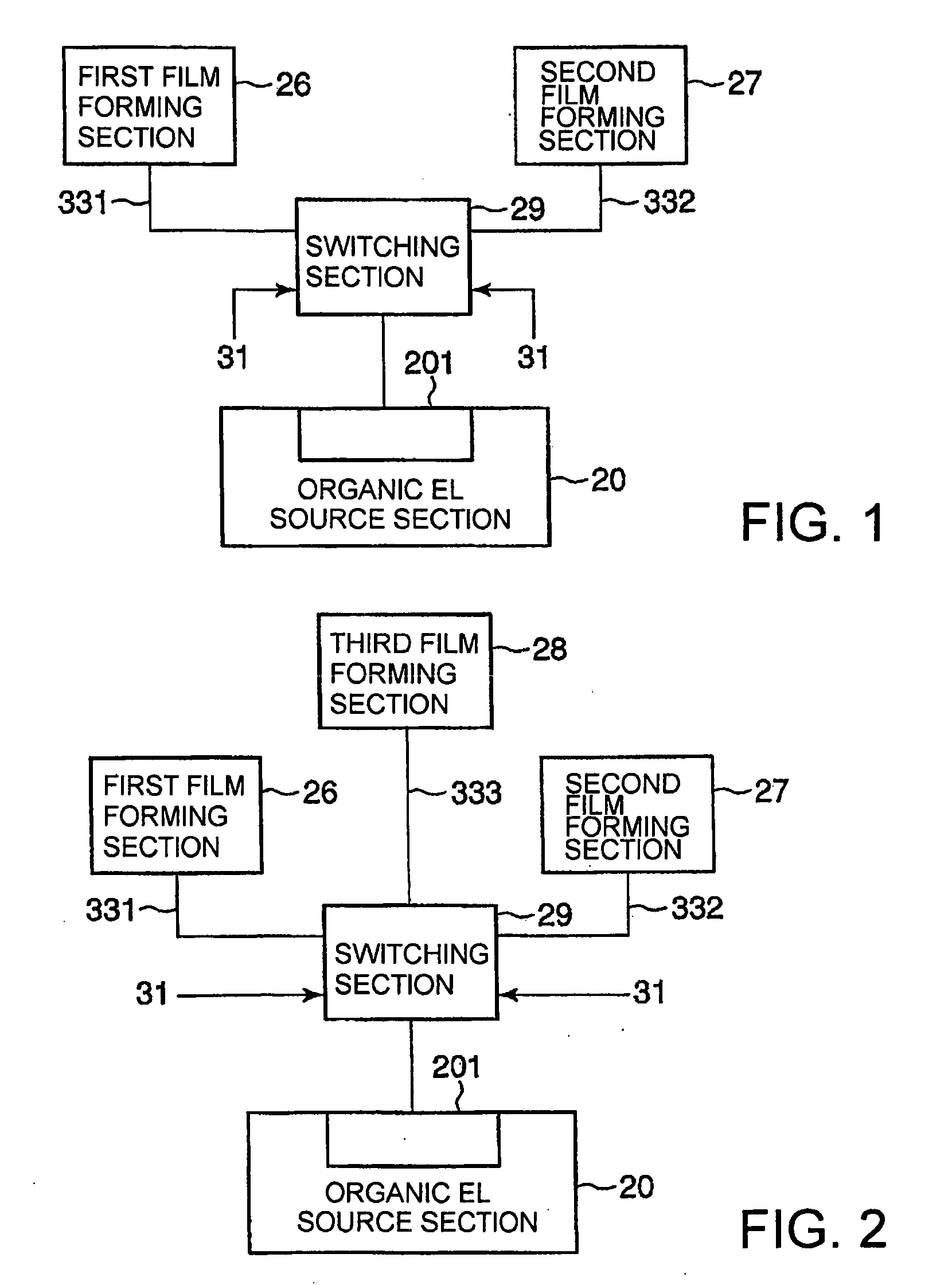
[0110]Referring to FIG. 1, a film forming apparatus according to this invention is schematically illustrated. The illustrated film forming apparatus comprises an organic EL source section 20 having a plurality of organic EL sources, first and second film forming sections 26 and 27, and a switching section 29 (switching means) for supplying an evaporated organic EL material from the organic EL source section 20 selectively to the first and second film forming sections 26 and 27. The switching section 29 comprises piping, orifices, mass controllers (flow control systems), valves, and so on. In this connection, the switching section 29 is controlled by a controller (not shown) that controls the valves, the orifices, the flow control systems, and the valves.

[0111]Specifically, the illustrated organic EL source section 20 has container sections (hereinafter referred to as raw material container sections) containing organic EL raw materials corresponding to the number of organic EL films ...

second embodiment

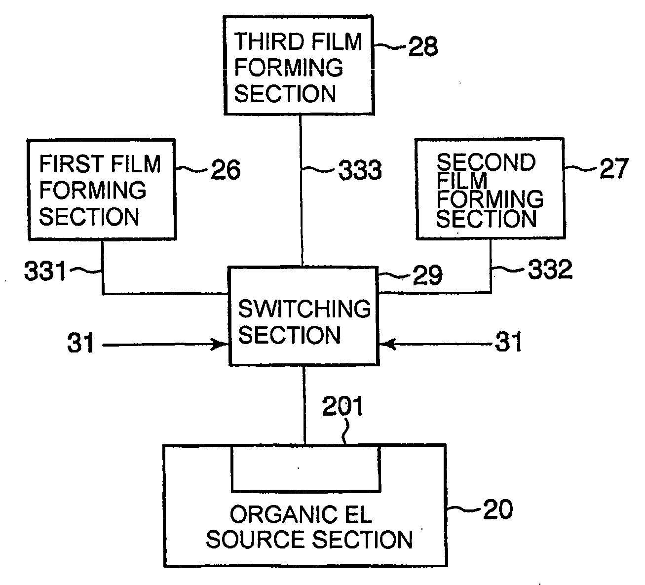
[0124]Referring to FIG. 2, there is shown a conceptual diagram of a film forming apparatus according to this invention. The illustrated example differs from the film forming apparatus of FIG. 1 in that an organic EL raw material from an organic EL source section 20 is individually supplied to three film forming sections, i.e. first to third film forming sections 26 to 28, through a switcher 29, while it is supplied only to the two film forming sections 26 and 27 in the film forming apparatus of FIG. 1. In the illustrated example, the third film forming section is connected to the switcher 29 through a piping system 333 and the piping system 333 is controlled in the same manner as the other piping systems 331 and 332.

[0125]At any rate, in the film forming apparatus shown in FIG. 2, an evaporated organic EL raw material from each raw material container section 201 is selectively supplied to the first to third film forming sections 26 to 28 through a switcher 29.

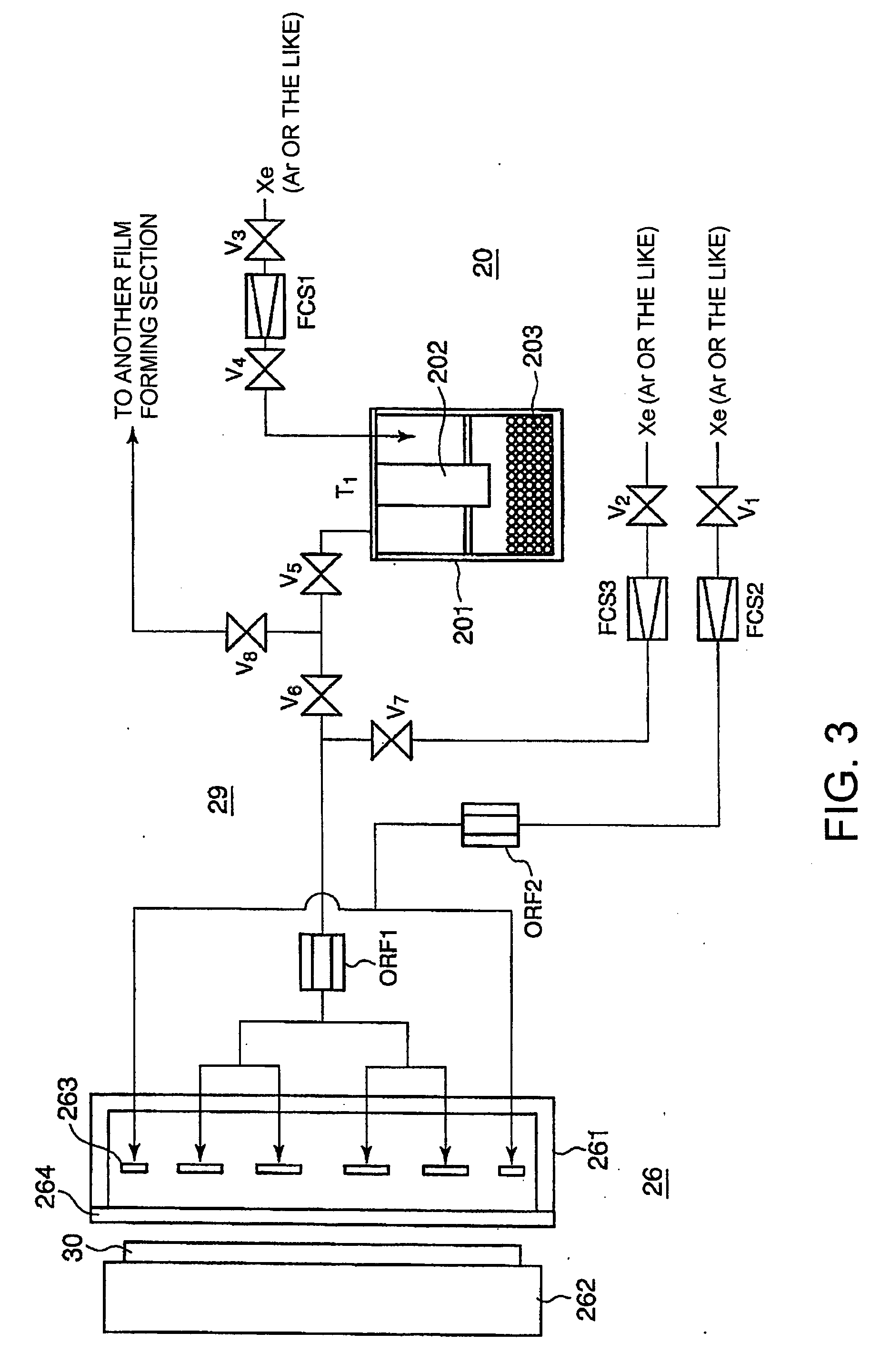
[0126]Referring to FIG....


PUM

PropertyMeasurementUnit
sizeaaaaaaaaaa
thicknessaaaaaaaaaa
thicknessaaaaaaaaaa

Abstract

Provided are an evaporating jig by which a thin film, especially an organic EL film, can be uniformly formed over a long time, and a film forming apparatus including the evaporating jig. The evaporating jig is provided with an evaporating pan, having a bottom plane and side planes arranged to stand from the bottom plane, for defining a material containing space opened inside the side planes; and partitioning plates for partitioning the material containing space into a plurality of partial spaces. The partitioning plates are provided with locking pieces having a height which permits the partial spaces to be continuous on a bottom plane side of the evaporating pan.

Description

TECHNICAL FIELD[0001]This invention relates to a film forming apparatus for forming a layer of a predetermined material, a jig for use in the film forming apparatus, and a measurement method using the jig and, in particular, relates to a film forming apparatus for forming a layer of a predetermined material by evaporating a raw material of the predetermined material, a jig for use in the film forming apparatus, and a measurement method using the jig.BACKGROUND ART[0002]A method of forming a layer of a predetermined material by evaporating a raw material of the predetermined material is widely used in the manufacture of semiconductor devices, flat panel display devices, and other electronic devices. A description will be given hereinbelow using an organic EL display device as one example of those electronic devices. The organic EL display device having a sufficient brightness and a lifetime of several tens of thousands of hours or more uses an organic EL element being a self-light-em...

Claims


Application Information

Patent Timeline
Patent Type & Authority Applications(United States)
IPC IPC(8): C23C16/00B05D5/12B05B7/00B05B7/16G01N33/00G06F19/00
CPCC23C14/12C23C14/246C23C14/243C23C14/548
Inventor OHMI, TADAHIROMATSUOKA, TAKAAKINAKAYAMA, SHOZOITO, HIRONORI
Owner TOHOKU UNIV
Why Eureka
Try Eureka