Device and method for vaporizing temperature sensitive materials

a temperature sensitive material and device technology, applied in the field of physical vapor deposition, can solve the problems of significant degradation, changes in the structure of the molecule and associated changes in the material properties, and the material is often subject to degradation, so as to reduce the risk of degrading, steady heater temperature, and steady vaporization rate

Active Publication Date: 2007-06-19
GLOBAL OLED TECH
View PDF20 Cites 38 Cited by
  • Summary
  • Abstract
  • Description
  • Claims
  • Application Information

AI Technical Summary

Benefits of technology

[0015]It is an advantage of the present invention that the device overcomes the heating and volume limitations of prior art devices in that only a small portion of organic material is heated to the desired rate-dependent vaporization temperature at a controlled rate. It is therefore a feature of the present invention to maintain a steady vaporization rate with a large charge of organic material and with a steady heater temperature. The device thus permits extended operation of the source with substantially reduced risk of degrading even very temperature sensitive organic materials. This feature additionally permits materials having different vaporization rates and degradation temperature thresholds to be co-sublimated in the same source.
[0016]It is a further advantage of the present invention that it permits finer rate control and additionally offers an independent measure of the vaporization rate.
[0017]It is a further advantage of the present invention that it can be cooled and reheated in a matter of seconds to stop and reinitiate vaporization and achieve a steady vaporization rate quickly. This feature minimizes contamination of the deposition chamber walls and conserves the organic materials when a substrate is not being coated.
[0018]It is a further advantage that the present device achieves substantially higher vaporization rates than in prior art devices without material degradation. Further still, no heater temperature change is required as the source material is consumed.
[0019]It is a further advantage of the present invention that it can provide a vapor source in any orientation, which is not possible with prior art devices.

Problems solved by technology

The organic materials used in the manufacture of OLED devices are often subject to degradation when maintained at or near the desired rate-dependent vaporization temperature for extended periods of time.
Exposure of sensitive organic materials to higher temperatures can cause changes in the structure of the molecules and associated changes in material properties.
In this manner, the material is consumed before it has reached the temperature exposure threshold to cause significant degradation.
The limitations with this practice are that the available vaporization rate is very low due to the limitation on heater temperature, and the operation time of the source is very short due to the small quantity of material present in the source.
The low deposition rate and frequent source recharging place substantial limitations on the throughput of OLED manufacturing facilities.
A secondary consequence of heating the entire organic material charge to roughly the same temperature is that it is impractical to mix additional organic materials, such as dopants, with a host material unless the vaporization behavior and vapor pressure of the dopant is very close to that of the host material.
This is generally not the case and, as a result, prior art devices frequently require the use of separate sources to co-deposit host and dopant materials.
A small change in source temperature leads to a very large change in vaporization rate.
Despite this, prior art devices employ source temperature as the only way to control vaporization rate.
These measures have the desired effect on steady-state vaporization rate stability but have a detrimental effect at start-up.
A further limitation of prior art sources is that the geometry of the vapor manifold changes as the organic material charge is consumed.

Method used


Image

  • Device and method for vaporizing temperature sensitive materials
  • Device and method for vaporizing temperature sensitive materials
  • Device and method for vaporizing temperature sensitive materials

Examples


second embodiment

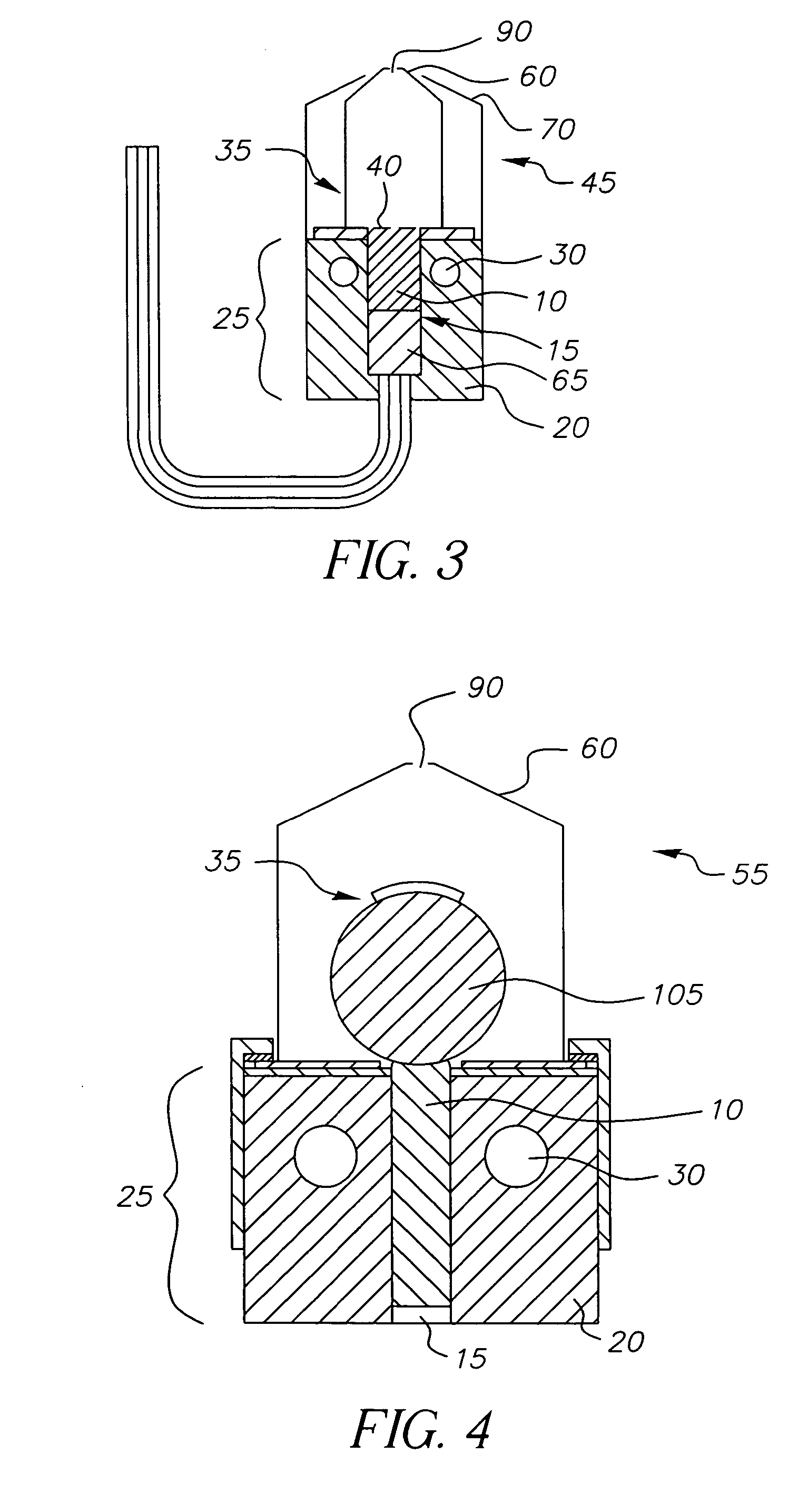
[0036]FIG. 3 shows a cross-sectional view of a device of this disclosure. Vaporization apparatus 45 includes first heating region 25, second heating region 35, base block 20, control passages 30, chamber 15, manifold 60, apertures 90, shields 70, and permeable member 40 as described above. Vaporization apparatus 45 does not include a piston, but instead includes liquid 65.

[0037]Organic material 10 can be as described above and is in close thermal contact with base block 20. Organic material 10 is metered at a controlled rate from first heating region 25 to second heating region 35, which is heated to a temperature above the vaporization temperature of organic material 10, or each of the components thereof. Organic material 10 is pushed against permeable member 40 through contact with a low vapor pressure liquid 65. Liquid 65 must be a liquid at the operating temperature of vaporization apparatus 45. For example, many organic materials commonly used in OLED devices have a vaporizatio...

third embodiment

[0040]FIG. 4 shows a cross-sectional view of a device of this disclosure. Vaporization apparatus 55 includes first heating region 25, base block 20, control passages 30, chamber 15, manifold 60, and apertures 90 as described above.

[0041]Organic material 10 can be as described above and is in close thermal contact with base block 20. Organic material 10 is pushed by either a piston or a liquid as described above against the periphery of rotating drum 105 and is carried as a fine powder film from first heating region 25 to second heating region 35. The powder can be attracted to the drum by electrostatic forces and rotating drum 105 can have surface features such as a knurled pattern or a pattern of small recesses having a definite volume in which a controlled volume of organic material 10 is contained so as to transport a fixed volume of powder. A wiper can optionally be used to remove excess powder from the surface of rotating drum 105. Rotating drum 105 is preferably constructed su...


PUM

PropertyMeasurementUnit
vaporization temperatureaaaaaaaaaa
pressureaaaaaaaaaa
work functionaaaaaaaaaa

Abstract

A method for vaporizing organic materials onto a substrate surface to form a film including providing a quantity of organic material into a vaporization apparatus and actively maintaining the organic material in a first heating region in the vaporization apparatus to be below the vaporization temperature. The method also includes heating a second heating region of the vaporization apparatus above the vaporization temperature of the organic material and metering, at a controlled rate, organic material from the first heating region into the second heating region so that a thin cross section of the organic material is heated at a desired rate-dependent vaporization temperature, whereby organic material vaporizes and forms a film on the substrate surface.

Description

CROSS REFERENCE TO RELATED APPLICATIONS[0001]Reference is made to commonly assigned U.S. patent application Ser. No. 10 / 352,558 filed Jan. 28, 2003 by Jeremy M. Grace et al., entitled “Method of Designing a Thermal Physical Vapor Deposition System”, the disclosure of which is herein incorporated by reference.FIELD OF THE INVENTION[0002]The present invention relates to the field of physical vapor deposition where a source material is heated to a temperature so as to cause vaporization and produce a vapor plume to form a thin film on a surface of a substrate.BACKGROUND OF THE INVENTION[0003]An OLED device includes a substrate, an anode, a hole-transporting layer made of an organic compound, an organic luminescent layer with suitable dopants, an organic electron-transporting layer, and a cathode. OLED devices are attractive because of their low driving voltage, high luminance, wide-angle viewing and capability for full-color flat emission displays. Tang et al. described this multilayer...

Claims


Application Information

Patent Timeline
Patent Type & Authority Patents(United States)
IPC IPC(8): C23C16/00C23C14/00C23C14/12C23C14/24H01J1/62H01L51/00H01L51/30
CPCC23C14/12C23C14/243H01L51/001H01L51/0081H01L51/0059H01L51/0077H10K71/164H10K85/631H10K85/30H10K85/324H05B33/10
Inventor LONG, MICHAELBROST, RANDOLPH C.GRACE, JEREMY M.FREEMAN, DENNIS R.REDDEN, NEIL P.KOPPE, BRUCE E.
Owner GLOBAL OLED TECH
Why Eureka
Try Eureka