Processing apparatus for processing object in vessel

Active Publication Date: 2005-12-22
CANON KK
View PDF11 Cites 6 Cited by
  • Summary
  • Abstract
  • Description
  • Claims
  • Application Information

AI Technical Summary

Benefits of technology

[0011] The present invention has been made based on the recognition of the above issues, and has as its object to prevent a temperature change in a vessel which

Problems solved by technology

When the gas as a heating medium does not exist, heat flow is limited to radiation and heat conduction through members that connect the devices and a vessel that accommodates the devices.
Even if temperature adjustment by heat conduction is possible, only some device in the vessel can be temperature-adjusted, and it is difficult to maintain the

Method used


Image

  • Processing apparatus for processing object in vessel
  • Processing apparatus for processing object in vessel
  • Processing apparatus for processing object in vessel

Examples


Example

First Embodiment

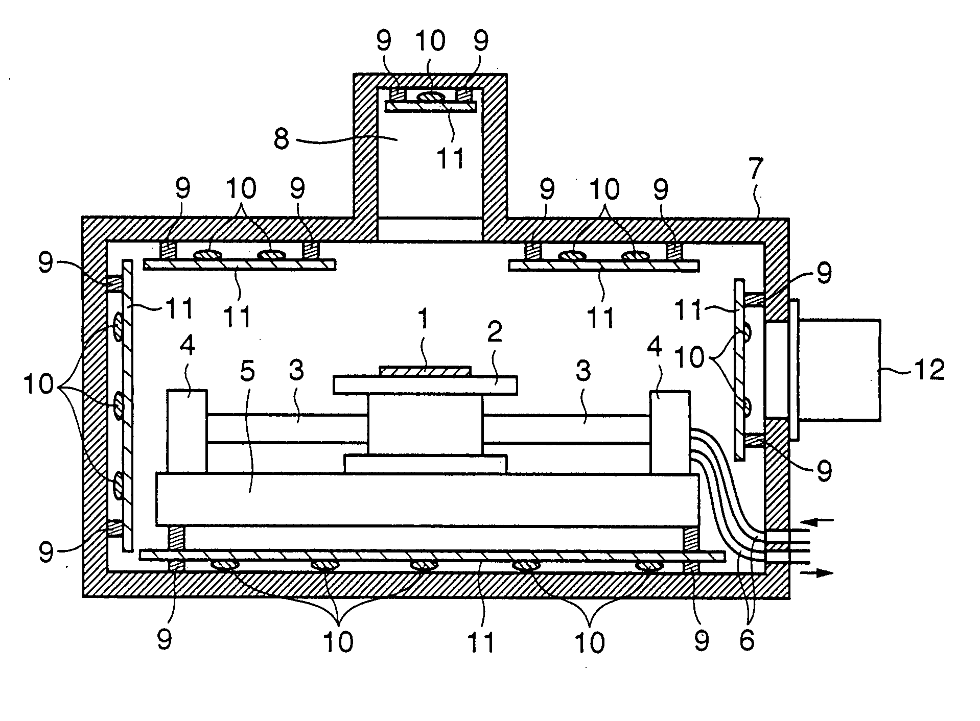
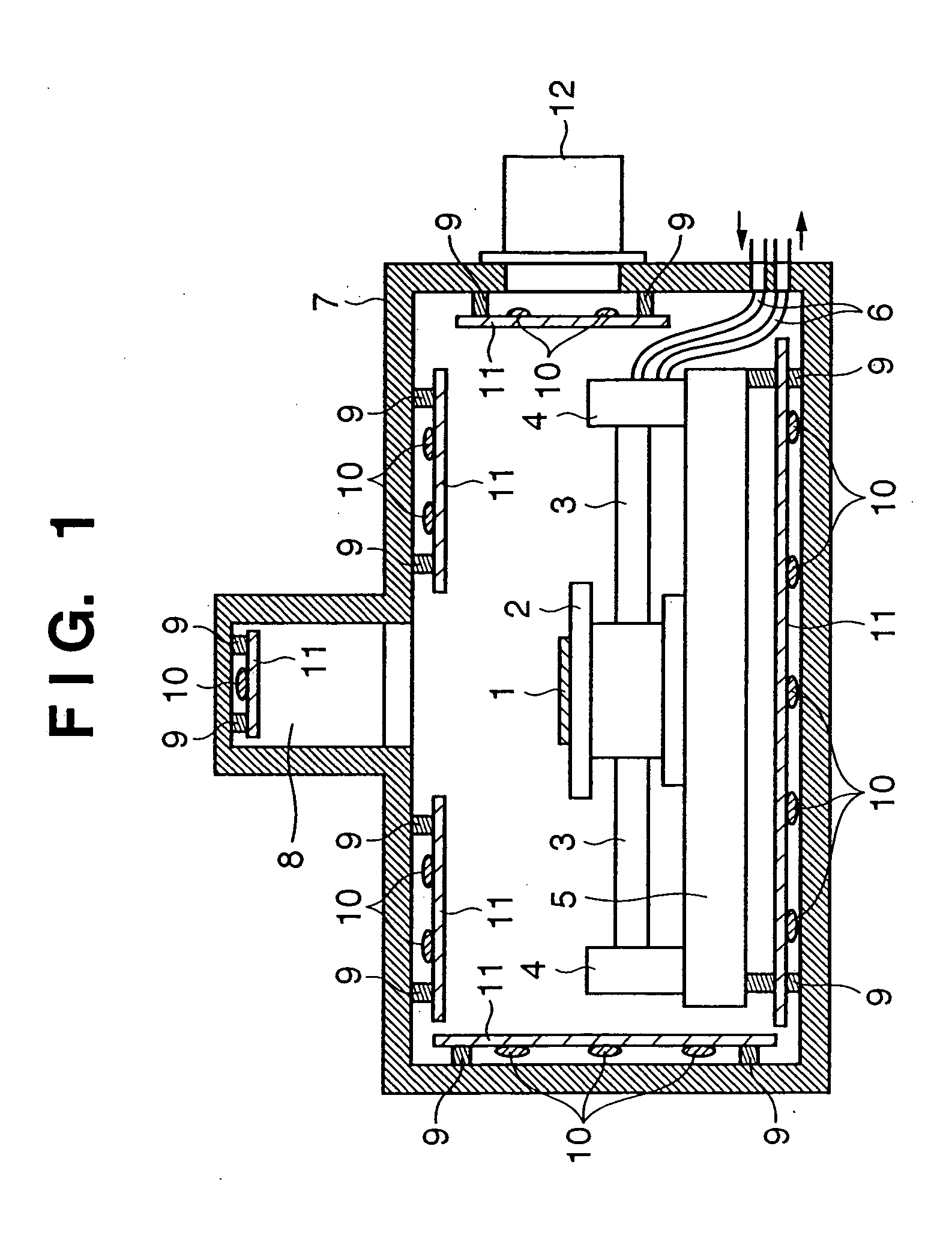
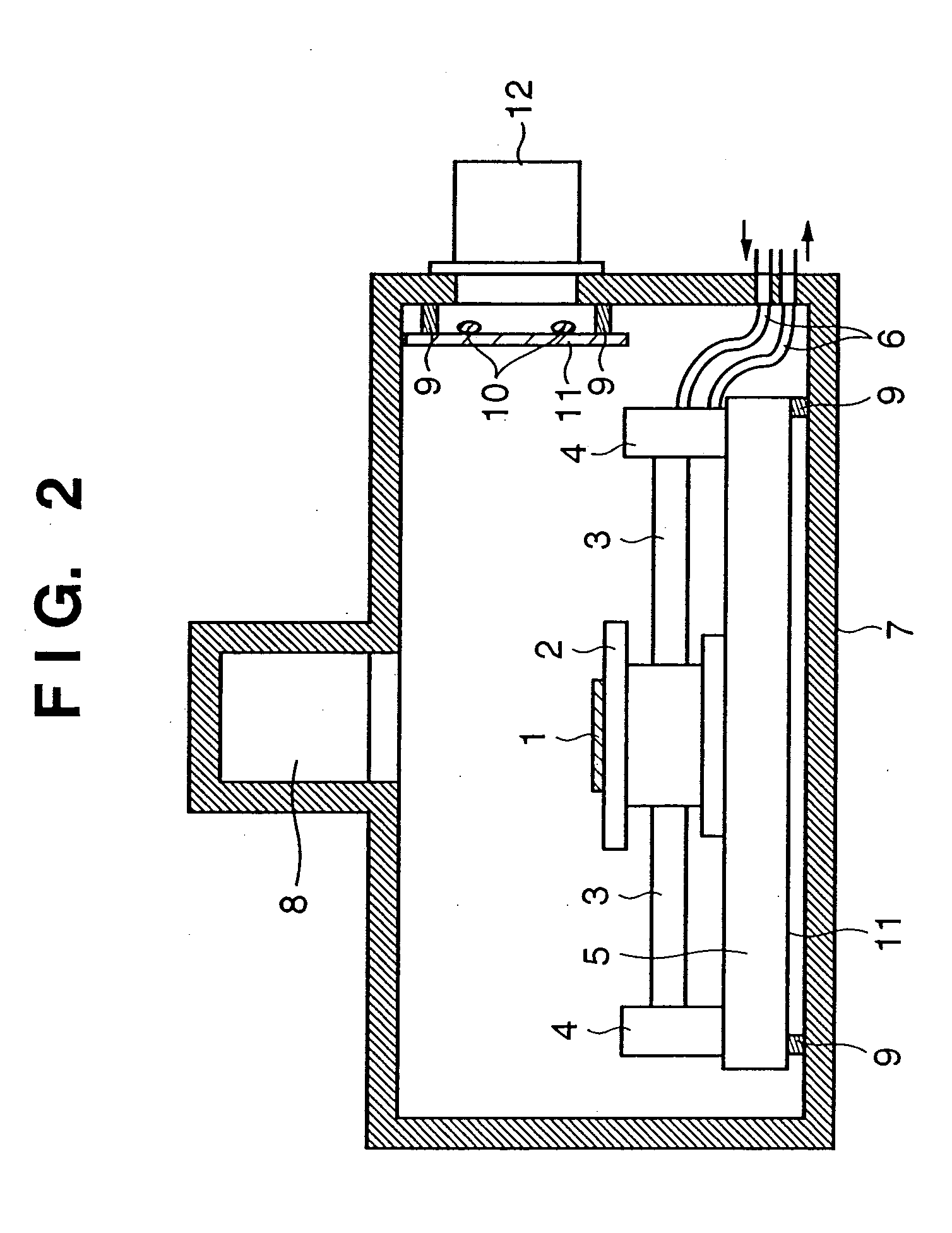
[0062] A temperature-controlled vacuum vessel for storing a target and maintaining the target at a constant temperature in a pressure-reduced or vacuum atmosphere, characterized by comprising: [0063] a temperature adjusting member provided to at least part in the temperature-controlled vacuum vessel; and [0064] a temperature adjusting mechanism which adjusts the temperature of the temperature adjusting member.

Example

Second Embodiment

[0065] A temperature-controlled vacuum vessel according to the first embodiment, characterized in that the temperature adjusting mechanism adjusts the temperature of the temperature-adjusting member by utilizing a refrigerant.

Example

Third Embodiment

[0066] A temperature-controlled vacuum vessel according to the first embodiment, characterized by further comprising a heat-insulating member which supports the temperature adjusting member in the temperature-controlled vacuum vessel.


PUM


Abstract

An apparatus for processing an object includes a vessel which forms a pressure-reduced inner space and accommodates the object, a member which is supported by an inner side of the vessel through a heat insulator, and a temperature adjusting portion which adjusts a temperature of the member.

Description

FIELD OF THE INVENTION [0001] The present invention relates to a technique for processing an object in a vessel and, for example, to a technique for maintaining an object at a constant, uniform temperature in a vessel that forms a pressure-reduced atmosphere such as a vacuum atmosphere. BACKGROUND OF THE INVENTION [0002] In a conventional temperature-controlled vessel, a temperature-adjusted gas medium is circulated in the vessel to set an apparatus in the vessel at the same temperature as that of the gas medium, so that the vessel serves as a temperature-controlled vessel. A prior art for an exposure apparatus that utilizes a temperature-controlled vessel will be described (see, e.g., Japanese Patent Laid-Open No. 10-154655). FIG. 9 is a schematic sectional view showing a temperature-controlled vessel in an exposure apparatus EO. The exposure apparatus EO has an exposure unit 114 having an illumination optical system, projection lens system, reticle stage, wafer stage, and the like...

Claims


Application Information

Patent Timeline
IPC IPC(8): C21B7/24G03B27/42G03C5/00G03F7/20H01L21/027
CPCG03F7/70716G03F7/70858G03F7/70841G03F7/70808
Inventor EMOTO, KEIJI
Owner CANON KK
Why Eureka
Try Eureka