[0028] Hereinafter, embodiments of the present invention will be described in detail with reference to the drawings.
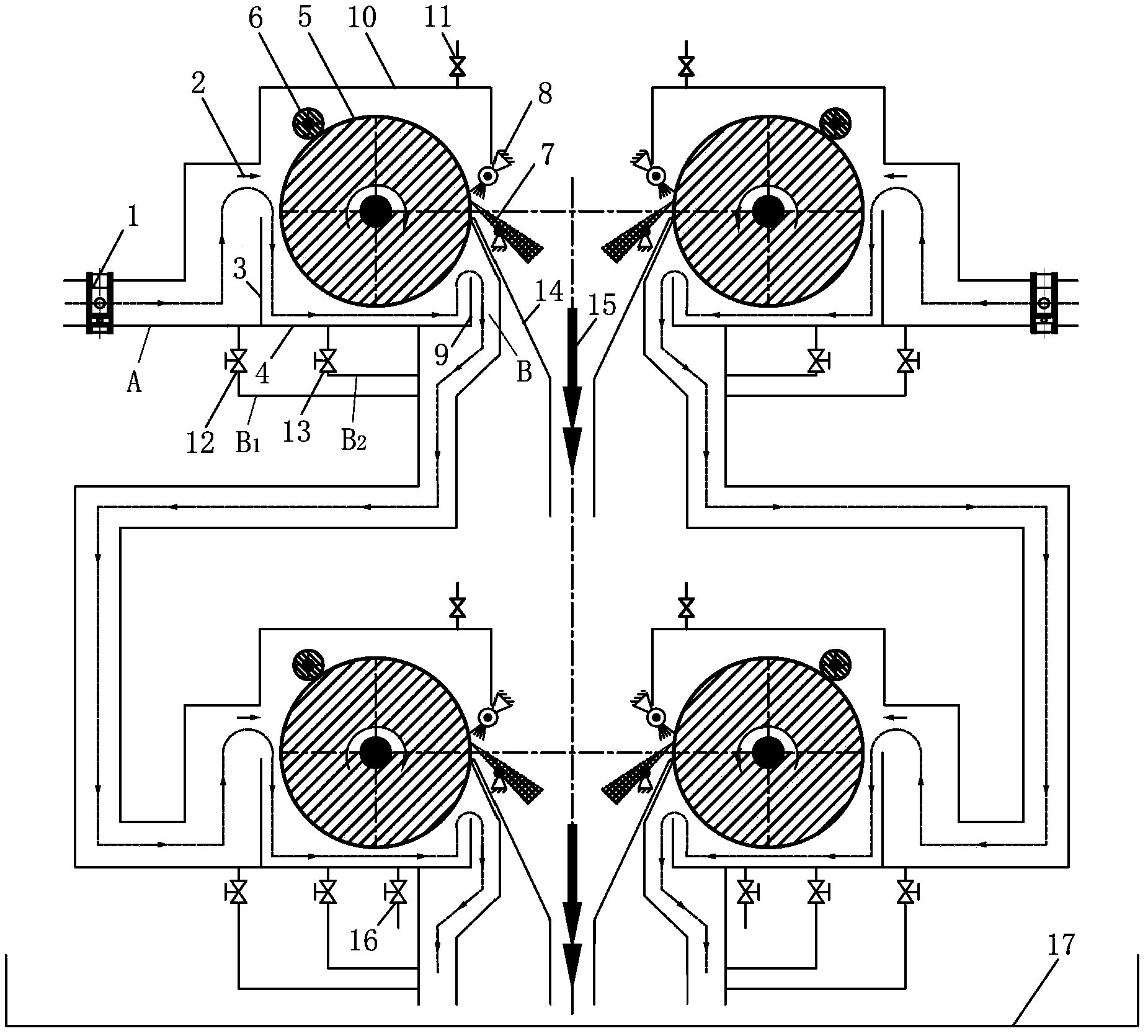
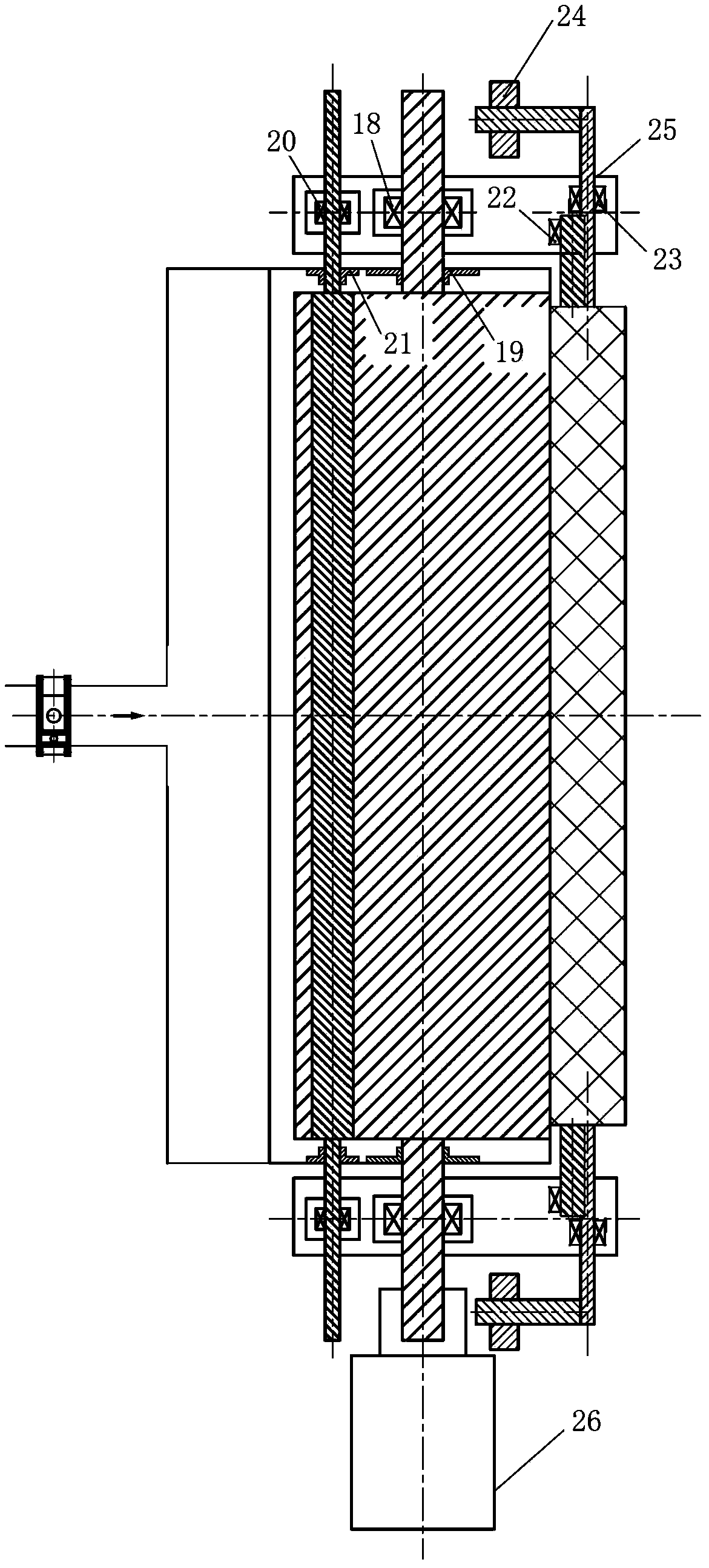
[0029] figure 1 It is a front sectional view showing the structure of the magnetic drum filter of the present invention, figure 2 It is an upper cross-sectional view showing the magnetic drum filter of the present invention.
[0030] The magnetic drum filter of the present invention can be used alone, or can be used in series in multiple stages, and the filtering effect can be improved when used in series. In addition, the magnetic drum filter of the present invention can also be used in parallel, and the cleaning agent circulation system can be subjected to two-way shunting treatment when in parallel. figure 1 The magnetic drum filter in series in two stages is shown in the case of being used in parallel. By using the magnetic drum filter constructed in this way, the cleaning agent circulation system can be divided into two ways, and each branch is processed in two ways. Level filtration.
[0031] Such as figure 1 , 2 As shown, the magnetic drum filter used for the continuous retreat and the cleaning section of the galvanizing unit includes a casing with an inlet A and an outlet B, a magnetic drum 5 arranged in the casing, and a magnetic drum 5 arranged in parallel It is also used for squeezing the squeezing roller 6 of the magnetic rotating drum 5, and a scraping roller device 7 used for scraping the iron filings and sundries on the magnetic rotating drum 5.
[0032] The inlet A of the casing is provided with a regulating valve 1, and the bottom of the casing is provided with a first partition plate 3 and a second partition plate 9 to form a tank 4 at the bottom of the casing.
[0033] In the shell, such as figure 1 As shown, the magnetic drum 5 is located on the upper side of the tank body 4, and the distance from the bottom of the tank body 4 to the magnetic drum 5 is less than 20 mm. And like figure 2 As shown, the magnetic rotating drum 5 is mounted on the bearing part 18, and the bearing part 18 of the magnetic rotating drum is located outside the tank 4 and supported by the bracket 25.
[0034] A magnetic rotating drum and a first sealing member 19 are installed on the shaft diameter of the magnetic rotating drum 5 to seal the cleaning agent and the cleaning agent vapor from leaking. The first seal 19 must not hinder the operation of the magnetic drum 5, but must also reliably seal the cleaning agent and steam, and at the same time have corrosion resistance.
[0035] The magnetic drum 5 is driven by a gear motor 26.
[0036] Such as figure 2 As shown, the squeeze roller 6 is mounted on the bearing component 20, and the squeeze roller bearing component 20 is located outside the trough 4 and is supported by the bracket 25. A squeeze roller and a second seal 21 are installed on the shaft diameter of the squeeze roller 6 to seal the cleaning agent and the cleaning agent vapor from leaking. In addition to not hindering the operation of the squeeze roller 6, the second sealing member 21 must also reliably seal the cleaning agent and steam, and have corrosion resistance.
[0037] Here, the bearing member 20 of the squeeze roller is configured as an elastic bearing member, so that the squeeze roller 6 abuts against the magnetic drum 5 and runs together. The squeeze roller 6 is made of magnetic resistant stainless steel 316L.
[0038] Such as figure 2 As shown, the scraper device 7 is installed on the scraper device support 23, and the scraper device support 23 is located outside the trough 4 and is supported by the bracket 25. The scraping roller device 7 is hinged and can swing at any angle.
[0039] The scraper device 7 is provided with a scraper device counterweight 24, and the scraper device 7 is pressed against the magnetic drum 5 by natural gravity. The counterweight 24 of the scraper roller device is divided into multiple pieces, and the force of the scraper roller device 7 against the magnetic drum 5 can be adjusted by the length of the screw rotation.
[0040] At the left and right sides of the first partition plate 3 at the bottom of the casing, a first branch pipe B1 and a second branch pipe B2 are respectively provided. The first branch pipe B1 and the second branch pipe B2 are respectively provided with a first slag discharge valve 12 and a second branch pipe. Two discharge valve 13.
[0041] A guide plate 14 for guiding the flow direction of the slurry is provided immediately below the scraper device 7, and the guide plate 14 guides the slurry to the waste liquid collecting tray 17 located on the lowermost side.
[0042] A steam exhaust valve 11 is provided on the upper part of the casing, and the steam exhaust valve 11 is used to discharge the steam generated by the cleaning agent.
[0043] A spray beam 8 is provided on the upper side of the scraper device 7 for spraying a certain amount of water to the surface of the magnetic drum to wash the iron filings and debris on the magnetic drum 5. The spray beam 8 is installed on a spray beam support 22. The spray beam support 22 is located outside the tank 4 and is supported by a bracket 25, and the spray direction can be adjusted at any angle.
[0044] The gear motor 26 is directly connected to the magnetic drum 5, and its torque is large and the speed is slow.
[0045] in figure 1 Among them, the cleaning agent with iron filings and debris enters the magnetic drum filter in two ways through two regulating valves 1. Before entering the magnetic drum filter, it is blocked by the front of the first partition plate 3 to slow down the cleaning agent. The flow rate, the cleaning agent flows along the cleaning agent flow direction 2, the cleaning agent turns over the first partition plate 3 into the tank 4, the iron filings and debris in the cleaning agent are adsorbed by the magnetic drum 5, and the magnetic drum 5 and The reverse rotation of the cleaning agent flow direction 2 brings the iron filings and debris adsorbed on the surface of the magnetic drum 5 to the position of the squeeze roller 6. The squeeze roller 6 squeezes the surface of the magnetic drum 5 to remove the iron filings and The cleaning agent in the debris is squeezed out.
[0046] The iron filings and debris from the magnetic drum 5 are then brought to the position of the scraping roller device 7, and the iron filings and debris are scraped to the guide plate 14 by the scraping roller device 7. When the scraper device 7 has an unsatisfactory scraping effect on the iron filings and debris on the surface of the magnetic drum, the unsatisfactory scraping effect of the scraper device 7 can be solved by opening the spray beam 8 and spraying a certain amount of water onto the magnetic drum 5. The problem.
[0047] The cleaning agent turns over the second partition plate 9 and enters the next stage magnetic drum filter.
[0048] The steam generated by the cleaning agent is discharged through the steam exhaust valve 11.
[0049] After the cleaning agent enters the magnetic drum filter from the regulating valve 1, the cleaning agent can enter the next stage of the magnetic drum filter through the first slag discharge valve 12 and the second slag discharge valve 13.
[0050] The iron filings and sundries falling on the guide plate 14 enter the waste liquid collecting tray 17 along the slurry flow direction 15.
[0051] The next level of magnetic drum filter is located below in terms of spatial position, and its structure and function are the same as the previous level of magnetic drum filter, except that an additional drain port 16 is added for maintenance, drainage and other cleaning of the magnetic filter. Agent filter interface is required.
[0052] The entire magnetic drum filter is located in the waste liquid collecting tray 17, and the waste liquid in the waste liquid collecting tray automatically flows back to the waste liquid pit.
[0053] In the present invention, the gear motor 26 used to drive the magnetic drum filter has a speed ≤ 10 r/min.
[0054] Such as figure 1 As shown, the height of the first spacer 3 of the magnetic drum filter is lower than the height of the axis of the magnetic drum 5, the height of the second spacer 9 is lower than the height of the first spacer 3, and the height of the second spacer 9 ensures The cleaning agent is soaked in the tank 4 at 1/5 of the height of the magnetic drum 5.
[0055] Such as figure 1 As shown, after the cleaning agent of the magnetic drum filter enters the magnetic drum filter, the iron filings and debris in the cleaning agent will accumulate at the bottom position of the first partition plate 3 and be brought to the The next level of magnetic drum filter is processed.
[0056] Such as figure 1 As shown, after the cleaning agent of the magnetic drum filter enters the magnetic drum filter, the iron filings and sundries in the cleaning agent will accumulate at the bottom of the tank 4 and be carried to the next through the second slag discharge valve 13 Grade magnetic drum filter for processing.
[0057] Such as figure 1 As shown, the magnetic flux of the magnetic drum 5 of the magnetic drum filter within the cleaning agent liquid level depth of 20 mm is greater than or equal to 8000 Gauss, and the magnetic drum 5 is made of magnetic resistant stainless steel 316L.
[0058] Such as figure 1 As shown, the magnets of the magnetic drum 5 of the magnetic drum filter are permanent magnets, which are evenly distributed along the circumference of the roller, and the distribution between the permanent magnet rings is staggered.
[0059] In the embodiment of the present invention, the housing may be an integral structure or an upper and lower split structure. When the shell is an upper and lower split structure, the upper and lower shells are connected with a sealing gasket.
[0060] In the present invention, the solution is solved by installing a magnetic drum filter on the cleaning agent circulation pipeline. Such as figure 1 , 2 As shown, for the continuous annealing unit: a set of magnetic drum filter can be installed in 1# hot alkali soaking tank and 1# hot alkali scrubbing tank, and one set in 2# hot alkali soaking tank and 2# hot alkali scrubbing tank. A set of magnetic drum filter, a set of magnetic drum filter in the electrolytic tank, and a set of magnetic drum filter in the 3# scrubbing tank. The configuration of this magnetic drum filter can affect the cleaning agent in the cleaning section. The iron filings and debris are fully filtered.
[0061] The invention utilizes the magnetic drum filter, according to the actual production requirements, through the optimized design of the structure and parameters of the magnetic filter, the iron filings and sundries in the cleaning liquid of the cleaning section of the continuous retreat and galvanizing unit can be quickly cleaned up, ensuring recycling use The reliable cleanliness of the cleaning fluid avoids the impact of iron filings and debris in the cleaning fluid on the surface quality of the strip steel, thereby improving the strip steel cleaning effect.