Filtering unit of side-air intake ultra-thin draught fan

A filter unit and fan technology, which is applied in the fields of dispersed particle filtration, space heating and ventilation details, household heating, etc. The effect of saving vertical space

Inactive Publication Date: 2011-10-05
HARBIN INST OF TECH
View PDF0 Cites 0 Cited by
  • Summary
  • Abstract
  • Description
  • Claims
  • Application Information

AI Technical Summary

Problems solved by technology

[0004] The purpose of the present invention is to solve the problems of the large vertical occupied space and limited application of the existing fan filter unit with longitudinal air guiding structure, and further provide a side-inlet ultra-thin fan filter unit

Method used


Image

  • Filtering unit of side-air intake ultra-thin draught fan
  • Filtering unit of side-air intake ultra-thin draught fan
  • Filtering unit of side-air intake ultra-thin draught fan

Examples


specific Embodiment approach 1

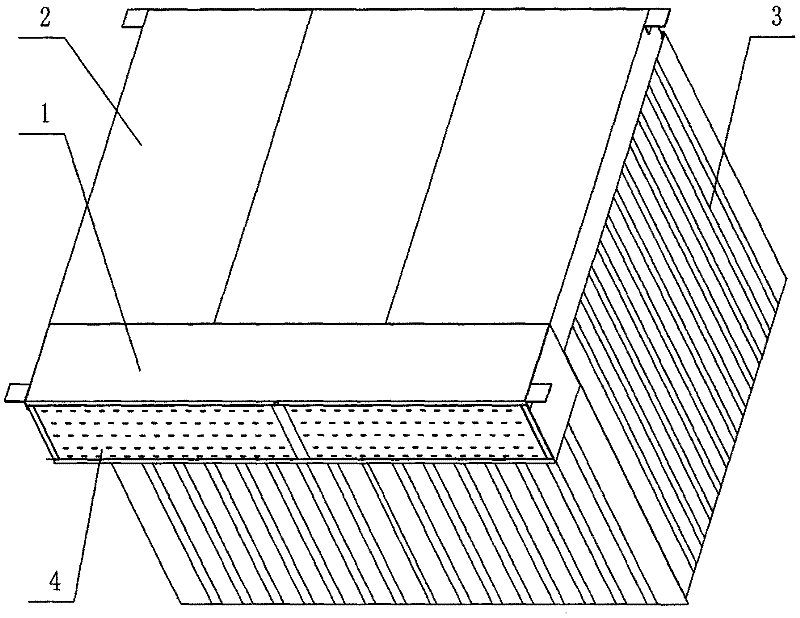
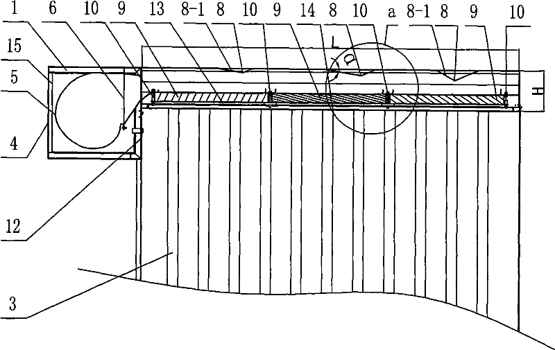
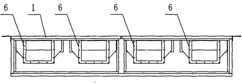
[0008] Specific implementation mode one: combine Figure 1 to Figure 6 Describe this embodiment, this embodiment includes air induction device and static pressure filtering device, and described air induction device is made up of fan box 1, multiple fans 5 and multiple transition flanges 6, and described static pressure filtering device is composed of static pressure The filter box 2, the support frame 13, a plurality of pressure equalizing baffles 8, a plurality of high-efficiency filters 9 and a plurality of filter compression mechanisms 10 are composed; the air inlet end plate 4 of the fan box 1 is a mesh plate, so The air outlet end plate 12 of the fan box 1 has a plurality of installation openings, and the plurality of fans 5 are arranged in the fan box 1 along the width direction of the fan box 1, and the outlet ends of the plurality of fans 5 pass through a plurality of transitions. The flange 6 is installed at the corresponding installation port on the air outlet end p...

specific Embodiment approach 2

[0009] Specific implementation mode two: combination Figure 7 ~ Figure 9 To illustrate this embodiment, the transition flange 6 of this embodiment is a deformed transition flange with a constant cross-sectional area, and the inlet end 6-1 to the outlet end 6-2 of the transition flange 6 are connected by a square truss 6-3, And the areas of the cross-sections of the transition flange 6 are equal. This arrangement eliminates additional wind pressure. Other compositions and connections are the same as in the first embodiment.

specific Embodiment approach 3

[0010] Specific implementation mode three: combination Figure 5 The present embodiment is described. The lower end plate 14 of the static pressure filter box 2 of the present embodiment has a hole diameter φ of punching holes of 3 mm to 5 mm. With such setting, the diffused flow effect is good and the operation is stable. Other compositions and connections are the same as in the first embodiment.


PUM


Abstract

A lateral air intake ultra-thin blower filtration unit relates to a blower filtration unit. The invention solves the problems in the prior blower filtration unit with a longitudinal wind guiding structure such as demand for large longitudinal space and suitability for occasions with limited space. The invention is characterized in that a plurality of blowers are arranged in the direction of the shortest side of a blower box in the blower box; air-out ends of the blowers are mounted in the position of the mounting port on an air-out end-plate through a plurality of transition flanges; an open end of a static pressure filtration box is mounted on the outer end surface of the air-out end plate of the blower box; a lower end plate of the static pressure filtration box is a complete current divergence plate with plate punching mesh holes; a plurality of efficient filters are mounted on a support skeleton in the direction of the longest side of the static pressure filtration box through a plurality of filter compressing mechanisms; and a plurality of pressure equalizing baffle boards are mounted in the direction of the longest side of the static pressure filtration box on the lower end surface of an upper end plate of the static pressure filtration box. The invention has the advantages that the main body structure is thin and is flexible to use. The invention is particularly suitable for being used for aloft operation and occasions with limited space.

Description

technical field [0001] The invention relates to a fan filter unit (FFU), which belongs to the technical field of air purification equipment. Background technique [0002] Air purification technology is an emerging industrial technology developed with the application requirements of the electronics and pharmaceutical industries. It has developed rapidly in recent years and has penetrated into more fields such as optics, biology, physics and micromechanics. At present, there are various types of air purification equipment. Among them, the fan filter unit (FFU) is a modular equipment that can be quickly assembled and disassembled according to the requirements of the purification area and level. It is flexible in operation and widely used. Sale. [0003] Most of the existing FFUs use unidirectional flow (laminar flow) to ensure the cleanliness level of the corresponding space on the air outlet surface, and adopt the following structural principle: Fresh air passes through the f...

Claims


Application Information

Patent Timeline
Patent Type & Authority Patents(China)
IPC IPC(8): B01D46/10F24F13/28
Inventor 朱成禹程强李文博吕志伟
Owner HARBIN INST OF TECH
Why Eureka
Try Eureka