Airflow management system

A technology for managing systems, air flow, applied to electrical components, lawn mowers, cooling/ventilation units, etc.

Active Publication Date: 2013-10-30
ROBERT BOSCH GMBH
View PDF6 Cites 14 Cited by
  • Summary
  • Abstract
  • Description
  • Claims
  • Application Information

AI Technical Summary

Problems solved by technology

[0003] Cooling fans have not been used in previous designs of battery-operated ro

Method used


Image

  • Airflow management system
  • Airflow management system
  • Airflow management system

Examples


Embodiment Construction

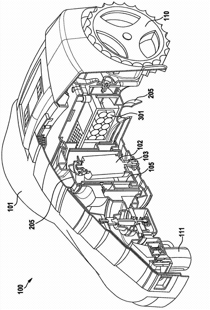
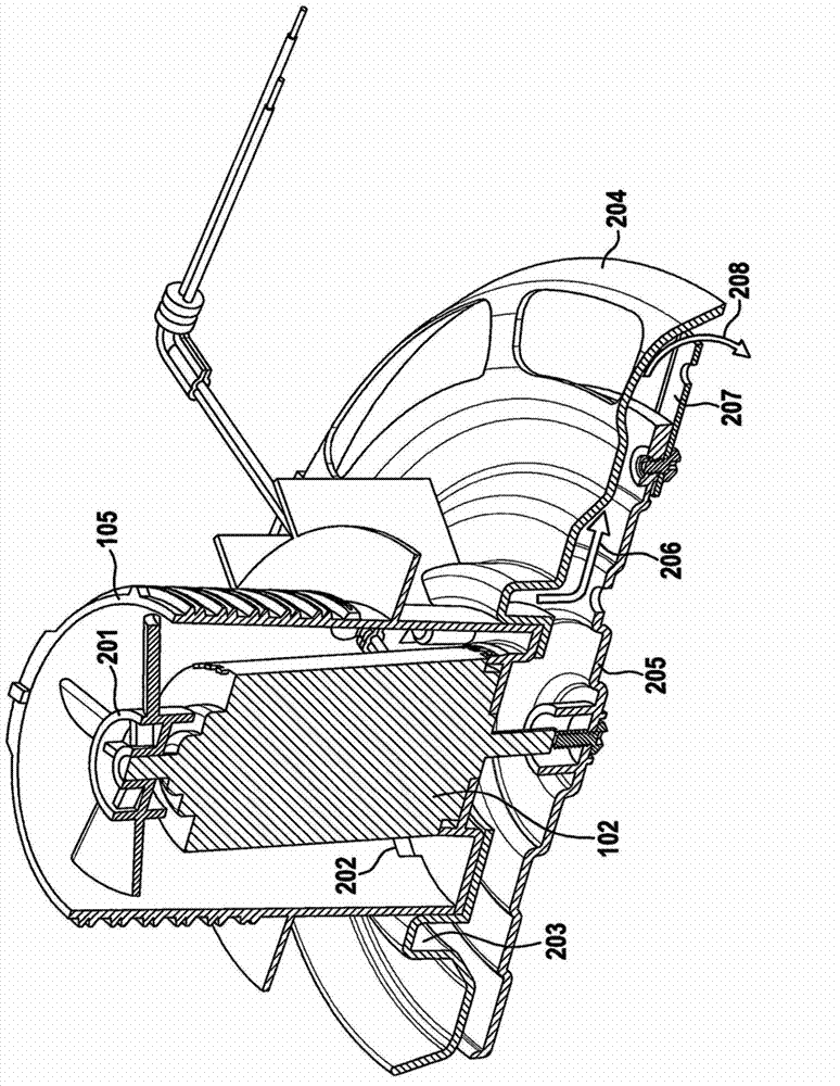
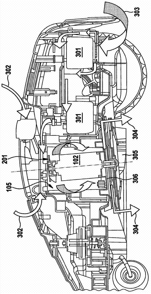
[0024] figure 1 A lawn trimmer 100 is shown having a housing part 101 , a drive motor 102 for driving a shaft 103 for attachment to a cutting disc 205 , and a gear 104 for driving a cooling fan 201 . Housing portion 105 with vents (not shown) houses the motor and cooling fan, and forms part of the underframe of the trimmer, thereby providing protection for other components of the trimmer such as the wheels 110, 111, battery pack 301 and control electronics. Provides a mount point.

[0025] In the illustrated embodiment of the invention, the front section of the trimmer is sufficiently sealed from moisture ingress because there are no components in this section that require cooling. The rear section is vented at selected locations to allow cooling during operation. This will be explained in more detail below. Ventilation is also provided at the top of the trimmer. Vents are located on the underside of the housing to protect the trimmer from the weather. In the described em...


PUM


Abstract

The present invention relates to an airflow management system, particularly for a lawn mower, especially a robotic lawn mower. We describe a battery-operated robotic lawn mower with an active airflow management system, said active airflow management system comprising: at least one first air vent (303) positioned on an underside of said mower; at least one second air vent (302); an internal housing surrounding a motor (102); a fan (201); and at least one cooling air channel located within said housing and around said motor. An air flow path is defined between the first (303) and the second (302) vents; and said at least one second vent (302) has a lower air flow capacity than an air flow capacity of said at least one cooling air channel, such that in operation, a greater volume of air is drawn through the first vent (303) than the second. (302)

Description

technical field [0001] The invention relates to an air flow management system, in particular for lawn trimmers, especially automatic lawn trimmers (also known as self-guided or free-standing trimmers). Background technique [0002] Existing lawn trimmer designs can be prone to overheating of electrical components due to high cutting loads, high ambient temperatures, or a combination of the two. Excessive heat can affect electronics and batteries, especially lithium batteries. This is especially true for automatic lawn trimmers. They are often outside in the sun most or all of the time, especially when they are docked to recharge batteries or simply wait for their next scheduled cutting operation. In the case of lithium batteries, the electronics in these devices are usually constructed to prevent product operation when the battery cells are above a certain extreme temperature (typically 70°C), with the aim of preventing permanent damage or, in extreme cases, catching fire....

Claims


Application Information

Patent Timeline
IPC IPC(8): A01D75/18A01D101/00
CPCA01D34/008H02K9/06A01D69/02
Inventor R·巴克斯特
Owner ROBERT BOSCH GMBH
Why Eureka
Try Eureka