
Detection and identification circuit

A technology for identifying circuits and branch circuits, which is applied in the field of detecting and identifying circuits and can solve problems such as time and labor waste.

Inactive Publication Date: 2013-10-30
HONG FU JIN PRECISION IND (SHENZHEN) CO LTD +1
View PDF5 Cites 4 Cited by
  • Summary
  • Abstract
  • Description
  • Claims
  • Application Information

AI Technical Summary

Problems solved by technology

At this time, the user needs to disconnect the power supply again, and re-insert the memory stick into the memory slot of the motherboard, which will result in a waste of time and manpower.

Method used


Image

  • Detection and identification circuit
  • Detection and identification circuit

Examples


Embodiment Construction

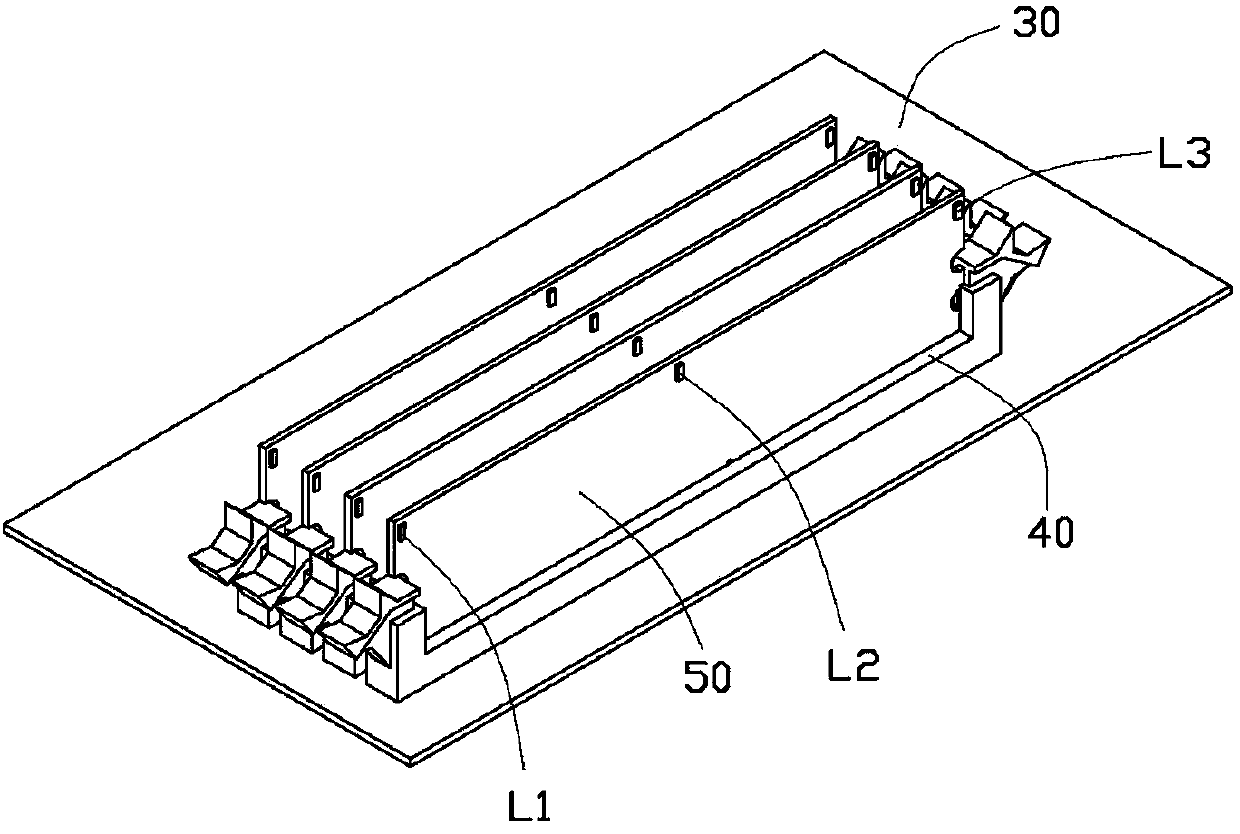
[0014] Please refer to figure 1 , the detection and recognition circuit of the present invention is used to indicate whether the memory stick 50 is plugged into the memory slot 40 when the memory stick 50 is plugged in, that is, whether the pins of the two are in good contact.

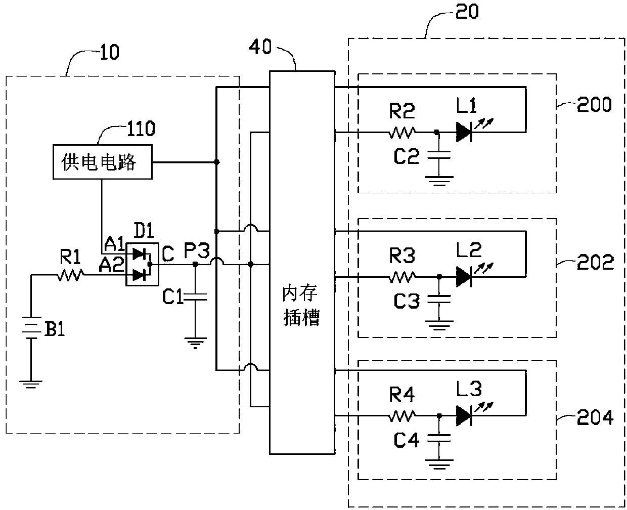
[0015] According to the pin distribution of the memory slot, each type of memory slot is provided with multiple undefined pins. Therefore, the present invention uses undefined pins in the memory slot, that is, idle pins.

[0016] Please continue to refer figure 2 , the preferred embodiment of the detection and identification circuit includes a power supply circuit module 10 and an indicator circuit module 20 . The power circuit module 10 is disposed on a main board 30 and is electrically connected to a plurality of idle pins of a memory slot 40 disposed on the main board 30 . The indicating circuit module 20 is disposed on a memory stick 50 and is electrically connected to gold fingers on the memor...


PUM


Abstract

A test circuit includes a power circuit module arranged on a motherboard of a computer and electrically coupled to first and second idle pins of a memory slot, and an indication module including a number of branch circuits. The indication module is arranged on a memory module. When the memory module is arranged in the memory slot properly, third idle pins of an edge connector of the memory module are electrically coupled to the first idle pins of the memory slot, respectively; and fourth idle pins of the edge connector of the memory module are electrically coupled to the second idle pins of the memory slot, respectively.

Description

technical field [0001] The invention relates to a detection and identification circuit, in particular to a circuit for detecting whether a memory is installed in place. Background technique [0002] As the price of memory sticks drops, more and more users hope to speed up the system by expanding the memory. When installing the memory stick, the user needs to pull out the power plug of the chassis, then open the chassis, and plug the memory stick into the memory slot on the motherboard. Then, power on and detect the motherboard to determine whether the memory module is plugged in place. However, during the process of inserting the memory stick into the memory slot, if the memory stick is not fully in contact with the memory slot, the motherboard will emit an abnormal alarm sound after the power is turned on. At this time, the user needs to disconnect the power again, and re-insert the memory stick into the memory slot of the main board, which will result in a waste of time ...

Claims


Application Information

Patent Timeline
Patent Type & Authority Applications(China)
IPC IPC(8): G06F11/27
CPCG06F13/409
Inventor 刘磊陈国义
Owner HONG FU JIN PRECISION IND (SHENZHEN) CO LTD
Learn More