Radiating device

A technology of a heat dissipation device and a heat dissipation element, which can be used in heating methods, household heating, household heating, etc., and can solve problems such as inconvenience

Inactive Publication Date: 2013-10-30
HONG FU JIN PRECISION IND (SHENZHEN) CO LTD +1
View PDF0 Cites 0 Cited by
  • Summary
  • Abstract
  • Description
  • Claims
  • Application Information

AI Technical Summary

Problems solved by technology

In this way, it is necessary to respectively fix the cooling element and the water receiving tray in the electronic device, and a fixed structure for fixing the water receiving tray should be provided at the position corresponding to the cooling element. When disassembling, the cooling element and the water receiving tray should be disassembled separately. very inconvenient

Method used


Image

  • Radiating device
  • Radiating device
  • Radiating device

Examples


Embodiment Construction

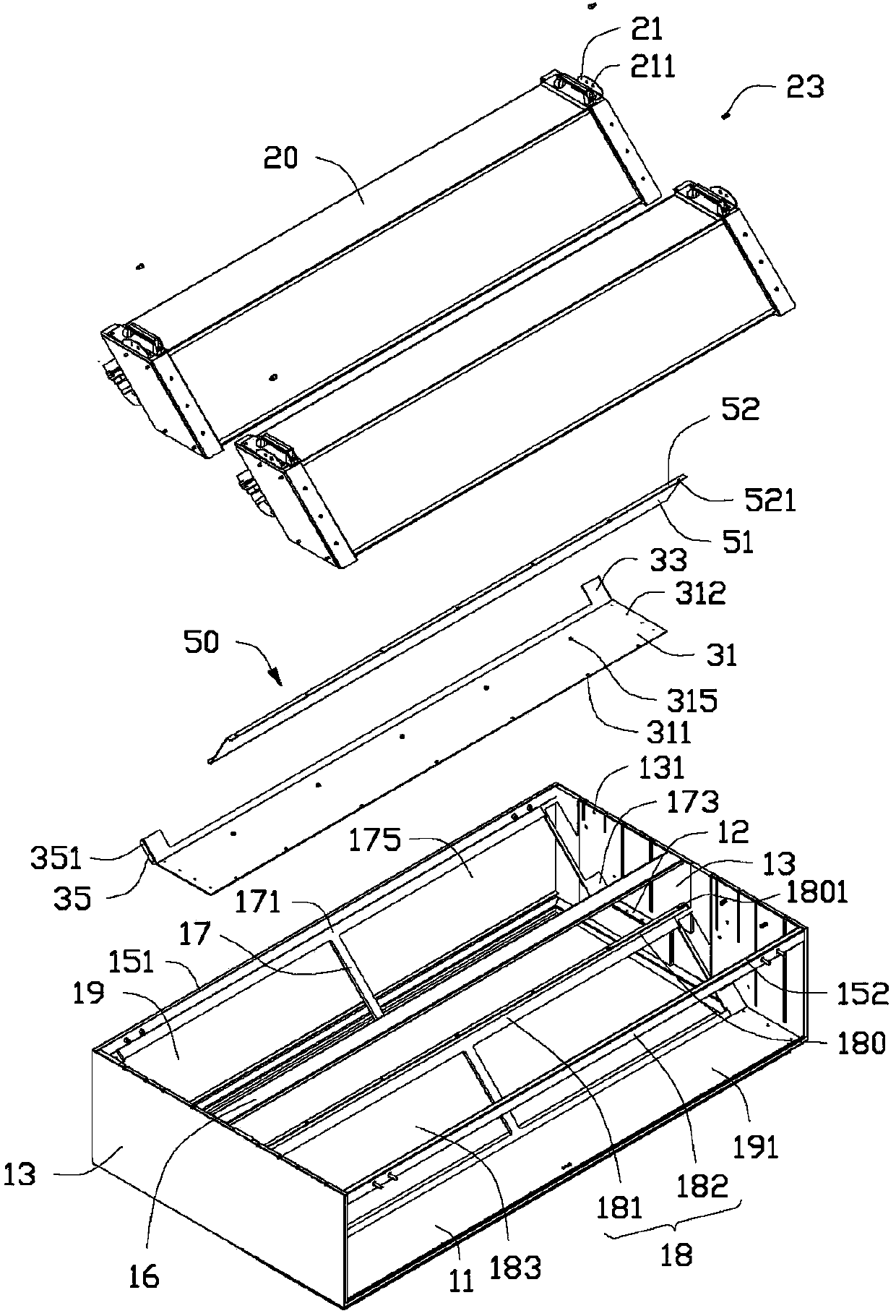
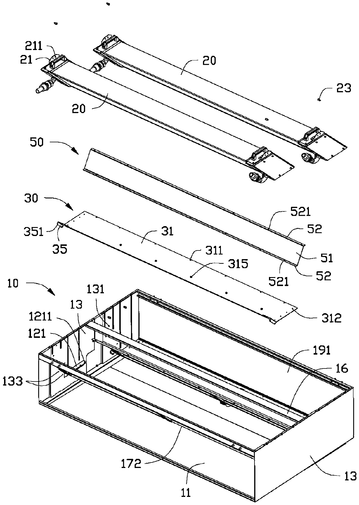
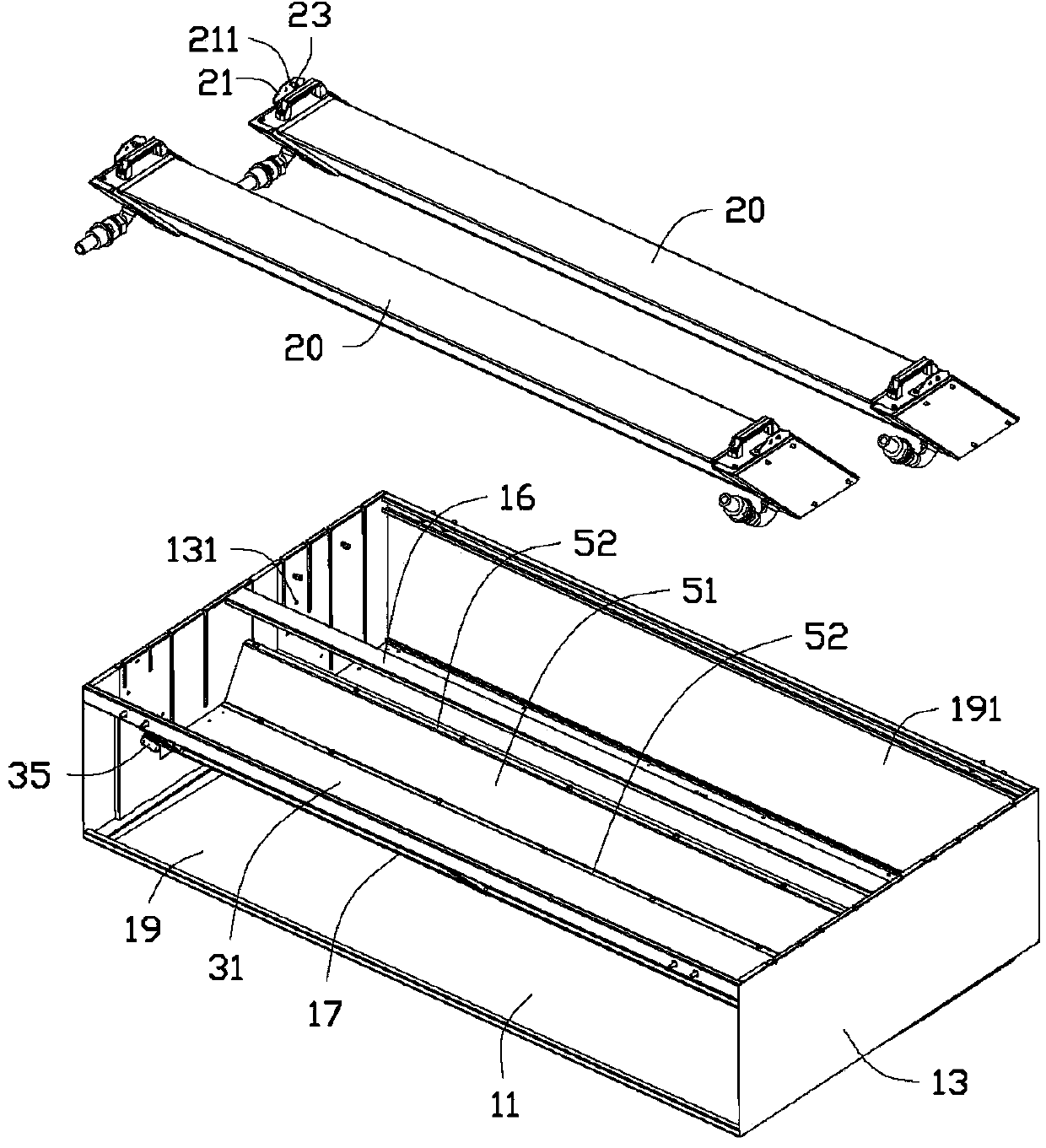
[0024] see figure 1 and figure 2 , In a preferred embodiment of the present invention, a heat dissipation device includes a housing 10 , two heat dissipation elements 20 , a support 30 and a partition 50 .

[0025] The housing 10 includes a bottom plate 11 and two opposite side plates 13 . In one embodiment, the bottom plate 11 is substantially perpendicular to the two side plates 13 . Described bottom plate 11 has certain slope, and offers a drainage hole 112 (such as Image 6 shown). The drain hole 112 is connected to a water outlet pipe (not shown in the figure) for draining the water in the casing 10 . A first beam 151 , a second beam 152 and an operation beam 16 are installed between the two side plates 13 . The first beam 151 and the second beam 152 are connected between side edges of the two side panels 13 that are substantially perpendicular to the bottom panel 11 . In one embodiment, the operating beam 16 is substantially parallel to the bottom plate 11 and is ...


PUM


Abstract

A heat dissipating device includes a chassis and a heat dissipating member. The chassis includes a bottom plate, two side plates, and a support plate. The two side plates are located on the bottom plate. The chassis defines an input opening and an output opening between the two side plates. The bottom plate defines a through hole. The support plate defines a ventilation opening and is located between the two side plates and between the input opening and the output opening. The heat dissipating member is secured to the support plate. An air flow path is defined from the input opening, the ventilation opening, via the heat dissipating member, to the output opening, and an water exit path is defined from the heat dissipating member to the bottom plate and configured to flow water from the heat dissipating member out of the chassis via the through hole.

Description

technical field [0001] The invention relates to a heat dissipation device, in particular to a heat dissipation device with a heat exchanger. Background technique [0002] In electronic devices such as large servers or containers, it is necessary to use multiple heat dissipation elements, such as heat exchangers, to dissipate heat. The two or more cooling elements are usually fixed on the casing of the electronic device for ventilation. Since each heat dissipation element has water droplets flowing down during the heat dissipation process, a water receiving tray is provided under each or more heat dissipation elements to prevent water droplets from dripping into the electronic device. In this way, it is necessary to respectively fix the cooling element and the water receiving tray in the electronic device, and a fixed structure for fixing the water receiving tray should be provided at the position corresponding to the cooling element. When disassembling, the cooling element ...

Claims


Application Information

Patent Timeline
IPC IPC(8): H05K7/20
CPCF24F7/00F24F13/222H05K7/20H05K7/20781
Inventor 杨旭
Owner HONG FU JIN PRECISION IND (SHENZHEN) CO LTD
Why Eureka
Try Eureka