Control unit, method and computer-readable medium for operating a ventilator

a control unit and ventilator technology, applied in the field of ventilators, can solve the problems of difficult to set a suitable level of pneumatic trigger, difficult to synchronize ventilation correctly with patient breathing efforts, and difficulty in adjusting the trigger level, so as to improve the trigger conditions

Inactive Publication Date: 2011-01-06
MAQUET CRITICAL CARE
View PDF18 Cites 69 Cited by
  • Summary
  • Abstract
  • Description
  • Claims
  • Application Information

AI Technical Summary

Benefits of technology

[0007]It is an object of the invention to improve the tri

Problems solved by technology

In some cases it is difficult to synchronize the ventilation correctly with the patient's breathing efforts.
For example, if there is a leakage, it will be difficult to set a suitable pneumatic trigger

Method used


Image

  • Control unit, method and computer-readable medium for operating a ventilator
  • Control unit, method and computer-readable medium for operating a ventilator
  • Control unit, method and computer-readable medium for operating a ventilator

Examples


Embodiment Construction

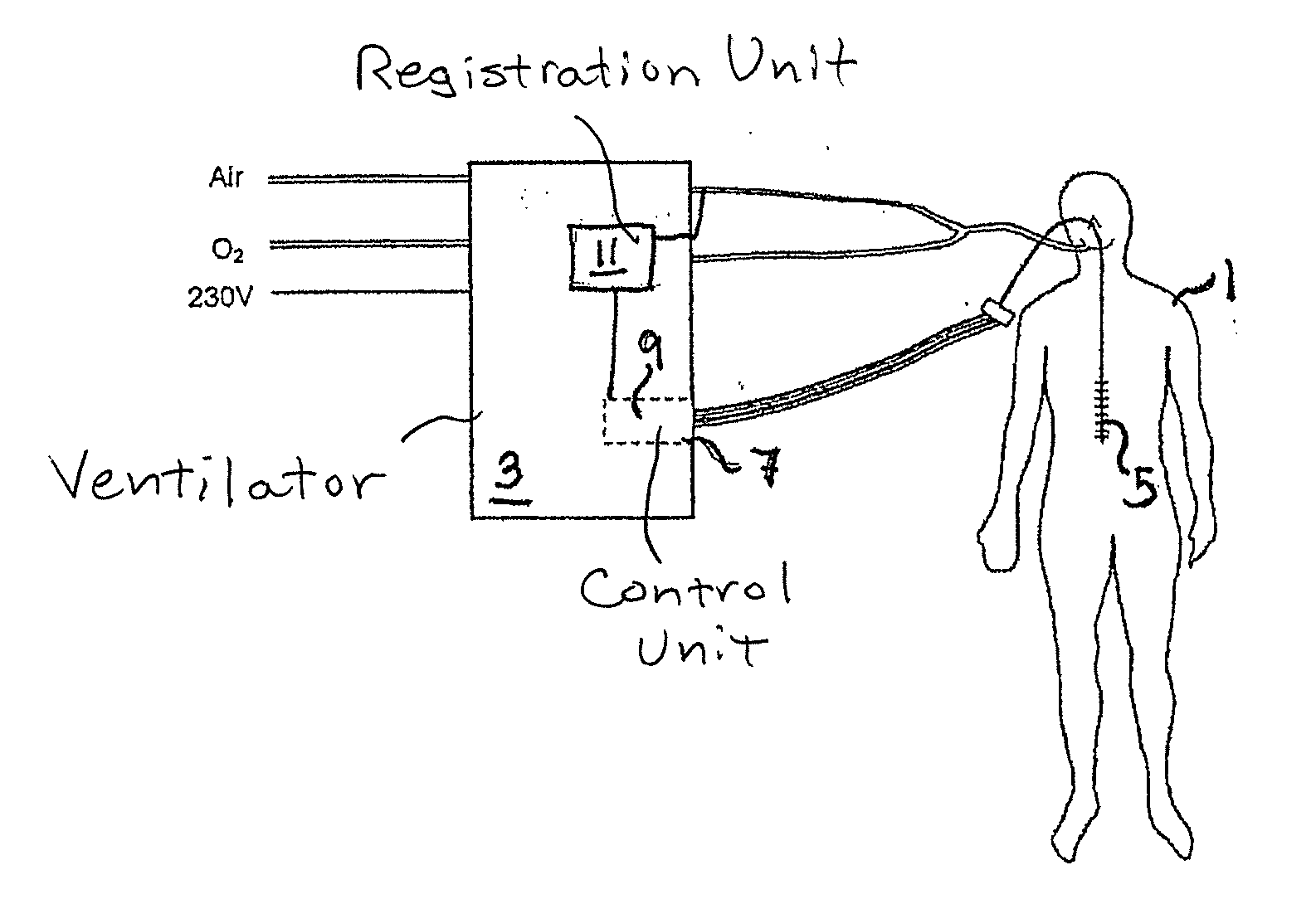
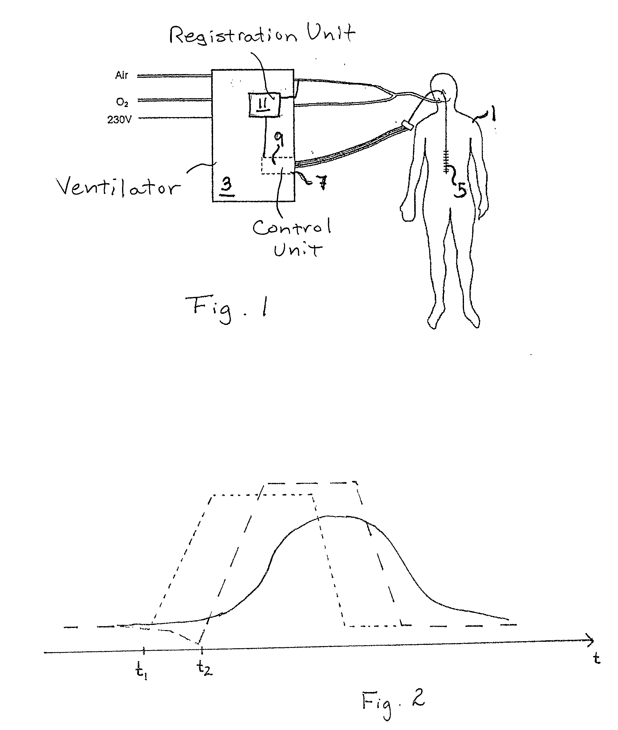
[0030]FIG. 1 is a schematic overview of a patient 1 connected to a ventilator 3. The ventilator is arranged to work in support mode but can also be arranged to work in a controlled mode. To capture the Edi signal, the patient 1 has an oesophageal catheter 5 inserted in order to record a myoelectric signal from the diaphragm. This myoelectric signal (EMG signal) is fed to a control input 7 of the ventilator 3 and processed in a control unit 9 in the ventilator to produce the overall signal, called an Edi signal. According to the invention, a bioelectric signal related to breathing, such as the Edi signal is used to adjust the pneumatic triggering criteria of the ventilator.

[0031]Typically the ventilator has registration unit 11 for monitoring the pressure and / or flow of breathing gas in the breathing circuit 1. The control unit 9 has a processor and at least one computer program that is executed to compare the patient's own breathing activity to the breathing support provided by the ...


PUM


Abstract

To set trigger conditions correctly in pneumatic mode, a ventilator is controlled to obtain a measurement value of a bioelectric signal representative of the patient's breathing function, determine, based on the bioelectric signal, at least one point in time at which the patient starts inhalation, obtain a measurement value to be used for triggering an inspiration phase in the ventilator during the at least one point in time, determine a trigger condition for the inspiration phase on the basis of the measurement value, and use the trigger condition for initiating inspiration when ventilating the patient in support mode.

Description

BACKGROUND OF THE INVENTION[0001]1. Field of the Invention[0002]The present invention relates to a ventilator for use in support mode and a method for ventilating a patient in support mode.[0003]2. Description of the Prior Art[0004]A ventilator for providing breathing support to a patient can work in different modes, depending, i.e. on the patient's condition. If the patient is showing some breathing activity a support mode is often suitable, in which the ventilator provides extra breathing support in phase with the patient's own breathing activity. In this case the patient's own breathing activity must be monitored in an appropriate way in order to synchronize the breathing support provided by the ventilator with the patient's own breathing so that an inspiration phase is started by the ventilator when the patient starts inhaling. Typically a pneumatic trigger condition based on pressure and / or flow in the ventilator is set.[0005]In some cases it is difficult to synchronize the ven...

Claims


Application Information

Patent Timeline
IPC IPC(8): A61M16/00
CPCA61B5/0488A61M2230/08A61M2230/00A61M16/00A61M16/024A61B5/389
Inventor LAKSOV, JOAKIMLAGERBORG, JOHAN
Owner MAQUET CRITICAL CARE
Why Eureka
Try Eureka