Reflection cup for secondary light distribution

A secondary light distribution and reflective cup technology, which is applied in the field of reflective cups, can solve the problems affecting the light irradiation effect and achieve low price, simple structure and good irradiation effect

Active Publication Date: 2013-11-13
ZHEJIANG JINGRI LIGHTING TECH
5 Cites 1 Cited by

AI-Extracted Technical Summary

Problems solved by technology

These secondary light distribution components will be connected with the circuit board (aluminum substrate) to form the required LED lamps. In many cases, multiple LED lamp beads and multiple secondary light distribution components are placed on the circuit board. To ensure that the light emitted by the lamps after combination is far enough, it is required that the secondary light distribution components...

Method used

And described vertical positioning part 201 is arranged on described gluing surface close to described horizontal locating part 202 places, in the present embodiment, what vertical locating part 201 adopted is positioning pin, and it is arranged on gluing surface on, and close to the positioning surface, the positioning surface is arc-shaped, adjacent to the glued surface, there is a height difference between them, the area ratio of the positioning surface to the glued surface is in the range of 1:6-1:4, with 1 :5 is better, to achieve the perfect combination of positioning and fixing.
The vertical positioning part 201 includes positioning pins or positioning blocks, and the positioning pins can adopt cylindrical pins, conical pins and diamond pins, etc., and set corresponding positioning holes on the circuit board (alumi...

Abstract

The invention discloses a reflection cup for secondary light distribution. The reflection cup comprises a reflection cup body with a reflection cavity, a positioning mounting part arranged on the reflection cup body for positioning the reflection cup body and a circuit board, and a fixing connection part arranged on the reflection cup body for fixedly connecting the reflection cup body and the circuit board. According to the connection fixing structure, the reflection cup body and the circuit board are well positioned by a vertical positioning part, and are fixed into a whole by the fixing connection part, so the reflection cup body does not incline after being connected with the circuit board and is vertical to the circuit board, and light rays are enabled to irradiate to a long distance, and a good irradiating effect is realized.

Application Domain

Light fasteningsReflectors

Technology Topic

Engineering

Image

  • Reflection cup for secondary light distribution

Examples

  • Experimental program(1)

Example Embodiment

[0028] The following descriptions are only preferred embodiments of the present invention, and do not limit the scope of the present invention.
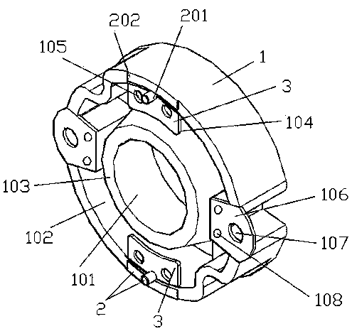
[0029] Examples, see attached figure 1 , A reflector cup for secondary light distribution, including a reflector cup body 1 with a reflector cavity 101, and a positioning and mounting portion 2 arranged on the reflector cup body 1 for positioning the reflector cup body 1 and the circuit board and settings A fixed connection part 3 on the reflective cup body 1 for fixedly connecting the reflective cup body 1 and the circuit board; the reflective cup body is generally a cylinder, and the axial section of the reflective cavity 101 is an inverted truncated cone shape , The surface is smooth, the positioning installation part 2 includes at least two vertical positioning parts 201 and a horizontal positioning part 202.
[0030] The vertical positioning part 201 includes positioning pins or positioning blocks. The positioning pins can be cylindrical pins, conical pins, diamond-shaped pins, etc. The circuit board (aluminum substrate) is provided with positioning holes corresponding to the position for easy installation, so that the reflective cup body and the circuit The board can be installed quickly and accurately, and the positioning block can adopt a square, polygonal or irregular shape; when the circuit board and the reflective cup body are connected, it is necessary to ensure that the reflective cup body and the circuit board are perpendicular. For this, we set The horizontal positioning portion 202 includes at least two flat surfaces protruding from the bottom surface of the reflective cup body 1, and protruding from the bottom surface of the reflective cup body 1 by 0.05-0.20mm, generally preferably 0.1mm ; In terms of quantity, it can also be three, four, five, six, etc. The quantity is selected according to actual needs and is generally set evenly.
[0031] After the reflector body and the circuit board are positioned, they need to be fixed together. The traditional fixing method is screw fixing, and screw fixing, the torque value of the screw is difficult to be the same, and the circuit board is relatively soft and has insufficient structural strength High, the different torque values ​​between the screws will cause the reflector cup and the circuit board to be non-vertical. In order to ensure that the irradiation is far enough, the reflector cups on the circuit board need to be parallel to each other, that is to say, each reflector cup body It must be perpendicular to the circuit board, so as not to affect the collection of light emitted by the LED lamp beads after passing through the reflector body. For this reason, we changed the traditional screw fixing connection method and fixed it with glue. The fixed connection part 3 includes at least Two glued surfaces, the glued surface is located above the horizontal positioning portion 202 and there is a 0.05-0.2 height difference with the horizontal positioning portion 202, the reason why the glued surface is located above the horizontal positioning portion, and horizontal positioning The height difference of the part is to avoid the influence of the glue on the positioning, because if the height is the same, when the glue is applied, the uneven thickness of the glue will affect the verticality of the reflector body and the circuit board, and our setting , Not only speeds up the application of glue, but also avoids the adverse effects caused by the thickness of the glue.
[0032] Furthermore, the bottom surface of the reflective cup body 1 is provided with a cavity 102. The cavity 102 is an annular cavity having a top surface, an outer side surface, and an inner side surface, and an inwardly extending rubber coating plate is provided on the outer side surface. 104, and the glue-coated surface is set on the glue-coated sheet 104, the thickness of the glue-coated sheet is between 0.5-1mm, the length is between 8-10mm, the width is 2-5mm, and the ratio of thickness to length is 1. :20-1:10; In this embodiment, the glue-coating plate is fan-shaped, and the glue-coating plate 104 is provided with glue overflow holes 105 communicating with the glue surface. The glue overflow holes 105 are through holes. It can be round hole, polygon hole, etc., the number is 2, 3, 4, 5, 6, 7, 8, etc. The existence of the overflow hole 105 can overflow the excess glue on the glued surface to avoid the thickness of the glue It affects the positioning of the reflective cup body and the circuit board. Furthermore, the rubber-coated plate 104 is an inclined plate, which extends inwardly from the outer side of the concave hole and extends upward at the same time, and forms an inclined angle with the horizontal positioning portion 202 , The inclination angle is 0.05-0.5°, of which 0.05° is the best, because after the glue dries, there is a downward pull force on the rubber-coated plate, in order to avoid the positioning of the reflector and the circuit board due to the deformation of the rubber-coated plate Influence, we let the rubber-coated board tilt upward to eliminate the adverse effects of the deformation of the rubber-coated board due to the drying of the glue.
[0033] The vertical positioning portion 201 is arranged on the glued surface close to the horizontal positioning portion 202. In this embodiment, the vertical positioning portion 201 adopts a positioning pin, which is arranged on the glued surface, and Close to the positioning surface, the positioning surface is arc-shaped, and it is adjacent to the glued surface, and there is a height difference between the positioning surface and the glued surface. The area ratio of the positioning surface to the glued surface ranges from 1:6 to 1:4, taking 1:5 as Good, to achieve the perfect combination of positioning and fixing.
[0034] The bottom surface 103 of the reflective cavity 101 is a flat surface, which is flush with the bottom surface of the reflective cup body 1. The reflective cavity 101 is used for secondary light distribution, so the surface is required, and the bottom edge is Due to the influence of processing accuracy, technology, equipment, etc., the surface is flawed, and we make the bottom surface of the reflective cavity 101 and the bottom surface of the reflective cup 1 flush, then the LED lamp beads will extend into the reflective cavity The part inside 101 makes the light emitted avoid the flawed part of the reflective cavity.
[0035] In order to supplement and fix the connection between the reflective cup body and the circuit board with screws when needed, the reflective cup body 1 is provided with a connecting seat 106 provided with a mounting hole 107, and the bottom surface of the connecting seat 106 is provided with two concave holes 108. The two concave holes have a diameter of 2mm and a depth of 0.25mm. Glue can be placed to play the role of bonding.
[0036] The above description is only an explanation of the present invention, so that those of ordinary skill in the art can fully implement the solution, but it is not a limitation of the present invention. After reading this specification, those skilled in the art can make no creativity in this embodiment as needed. Contributed changes, these are not creative changes. However, as long as the invention is within the scope of the claims, it is protected by the patent law.

PUM

no PUM

Description & Claims & Application Information

We can also present the details of the Description, Claims and Application information to help users get a comprehensive understanding of the technical details of the patent, such as background art, summary of invention, brief description of drawings, description of embodiments, and other original content. On the other hand, users can also determine the specific scope of protection of the technology through the list of claims; as well as understand the changes in the life cycle of the technology with the presentation of the patent timeline. Login to view more.

Similar technology patents

Mirror front lamp

InactiveCN106500005ALight evenlyGood irradiation effect
Owner:中山市荣亮照明有限公司

Novel operation shadowless lamp

PendingCN113236997Ahigh degree of automationGood irradiation effect
Owner:中国人民解放军海军特色医学中心 +1

Hidden rack lifting type illuminating mechanism

InactiveCN107270252AGood irradiation effect
Owner:FOSHAN HUAPU RUILIAN ELECTROMECHANICAL TECH CO LTD

Body condition measuring device

InactiveUS20050234351A1simple structure
Owner:DENSO CORP

Magnetic cooling apparatus and control method thereof

ActiveUS20130180263A1simple structure
Owner:SAMSUNG ELECTRONICS CO LTD

Dual-Drivetrain of Power-Assist Vehicle

InactiveUS20100181130A1enhance uphill momentumsimple structure
Owner:CHOU WEN CHENG

Direct type panel lamp

PendingCN112483940AGood irradiation effectlow production cost
Owner:SHANGHAI HONGBAO LIGHTING

Classification and recommendation of technical efficacy words

  • Simple structure
  • Good irradiation effect

Sharing system for air-conditioning coat

InactiveCN107440179ASimple structureeasy to wear
Owner:QINGDAO HAIER AIR CONDITIONER GENERAL CORP LTD

Feeding device of sorter of batteries plate

InactiveCN101357717ASimple structurecooperate well
Owner:NANJING NORMAL UNIVERSITY

Emergency parachuting device and method for multiple-rotor unmanned aerial vehicle

InactiveCN103895870Aavoid aircraft crashSimple structure
Owner:SOUTH CHINA AGRI UNIV +1

Hidden rack lifting type illuminating mechanism

InactiveCN107270252AGood irradiation effect
Owner:FOSHAN HUAPU RUILIAN ELECTROMECHANICAL TECH CO LTD

Direct type panel lamp

PendingCN112483940AGood irradiation effectlow production cost
Owner:SHANGHAI HONGBAO LIGHTING

Mirror front lamp

InactiveCN106500005ALight evenlyGood irradiation effect
Owner:中山市荣亮照明有限公司

Novel operation shadowless lamp

PendingCN113236997Ahigh degree of automationGood irradiation effect
Owner:中国人民解放军海军特色医学中心 +1
Why Eureka
Try Eureka