Pucch resource mapping, configuration method and device, user equipment, base station

A technology of resource mapping and user equipment, applied in the field of communication, can solve problems such as conflicting mapping positions

Inactive Publication Date: 2017-12-12
ZTE CORP
View PDF5 Cites 0 Cited by
  • Summary
  • Abstract
  • Description
  • Claims
  • Application Information

AI Technical Summary

Problems solved by technology

[0016] Aiming at the problem of how to avoid conflicts with traditional PUCCH mapping positions after the introduction of dynamic frame structures in versions after R11 in related technologies, no effective solution has been proposed yet

Method used


Image

  • Pucch resource mapping, configuration method and device, user equipment, base station
  • Pucch resource mapping, configuration method and device, user equipment, base station
  • Pucch resource mapping, configuration method and device, user equipment, base station

Examples


Embodiment 1

[0063] In this embodiment, the following method is used to dynamically configure the frame structure of the UE: the base station dynamically configures the frame structure of the current frame through broadcast signaling, and at the same time uses dedicated control signaling to instruct the UE to use the SIB-1 frame structure or the broadcast signaling indicates frame structure. The frame structure allocated to the R12UE may be different from the frame structure currently actually used by the eNB.

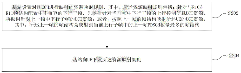
[0064] figure 2 It is a flowchart of a physical uplink control channel resource mapping configuration method according to Embodiment 1 of the present invention. This method is applied to the PUCCH format 1 / 1a / 1b for downlink subframes incompatible with the R10 / R11 frame structure configuration fed back by the specified uplink subframe in the TDD dynamic frame structure scenario. Such as figure 2 As shown, the method includes:

[0065] Step S202, the base station sets resource...

Embodiment 2

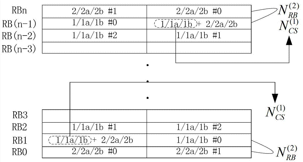
[0085] In this embodiment, for the resource mapping scheme of PUCCH, for the convenience of description, the following definitions are made:

[0086] PUCCH format 1 / 1a / 1b for "traditional PDCCH in R10-incompatible downlink subframes" fed back by an uplink subframe in a TDD dynamic frame structure scenario: PUCCH format 1d; a certain TDD dynamic frame structure scenario The PUCCH format 1 / 1a / 1b for the "EPDCCH in the R10 incompatible downlink subframe" fed back by the uplink subframe: PUCCH format 1e.

[0087] This embodiment is aimed at a UCI mapping scheme for a dynamic TDD frame structure allocation scenario (assuming R12 or a later version supports this scenario).

[0088] In order to better understand this embodiment, the problems encountered in UCI mapping in TDD traffic adaptive interference management (InterferenceManagement Traffic Adaptation, referred to as IMTA) will be described below: the existing standard UCI 1 / 1a / 1b adopts channel Mapping is performed in a selec...

Embodiment 3

[0103] Figure 7 It is a flowchart of a physical uplink control channel resource mapping configuration method according to Embodiment 3 of the present invention. This method is applied to PUCCH format 1 / 1a / 1b of EPDCCH, such as Figure 7 As shown, the method includes:

[0104] Step S702, the base station sets a resource mapping rule for mapping the PUCCH, wherein the resource mapping rule includes: inserting UCI resources corresponding to the PUCCH format 1 / 1a / 1b of the EPDCCH into UCI2 / 2a / 2b and UCI 1 / 1a Position between / 1b;

[0105] In step S704, the base station delivers the resource mapping rule to the UE.

[0106] Through the above process, the PUCCH is mapped according to the resource mapping rule of inserting the UCI resource corresponding to the PUCCH format 1 / 1a / 1b of the EPDCCH into the position between UCI2 / 2a / 2b and UCI1 / 1a / 1b, therefore, It can also avoid conflicts with traditional PUCCH mapping positions after the dynamic frame structure is introduced.

[0...


PUM


Abstract

The present invention provides a PUCCH resource mapping and configuration method and device, user equipment, and a base station, wherein the configuration method includes: the base station sets a resource mapping rule for mapping the PUCCH, and the resource mapping rule includes: for the R10 / R11 frame For incompatible downlink subframes in the structural configuration, first map the UCI resources for the downlink subframe in the current frame, and then map the UCI resources for the downlink subframe in the previous frame; or map the UCI of the UE according to the frame structure of the previous frame Resources, wherein the frame structure of the previous frame is the frame structure with the largest number of PDSCHs in the previous frame mapped to the current uplink subframe; the base station sends resource mapping rules to the UE. By adopting the above solution, conflicts with traditional PUCCH mapping positions are avoided.

Description

technical field [0001] The present invention relates to the communication field, in particular, to a PUCCH resource mapping and configuration method and device, user equipment, and a base station. Background technique [0002] In the existing standards of Long-Term Evolution (LTE for short) and Long-Term Evolution Advance (LTE-Advance for short), the physical uplink control channel (Physical Uplink Control Channel, PUCCH for short) resource The mapping is determined in the following 2 ways: [0003] If the PUCCH is format 1 / 1a / 1b, its resource mapping position is determined according to the index of the Physical Downlink Control Channel (PDCCH for short) scheduled by the corresponding PDSCH; [0004] If the PUCCH is format 2 / 2a / 2b, its resource mapping position is configured by high-layer signaling; [0005] In addition, in the existing standard, the resources of the PUCCH in the format 2 / 2a / 2b are mapped on the outermost side of the bandwidth, and then the PUCCH in the fo...

Claims


Application Information

Patent Timeline
Patent Type & Authority Patents(China)
IPC IPC(8): H04L5/00H04L1/18
CPCH04W72/23
Inventor 张晓博戴博梁春丽
Owner ZTE CORP
Why Eureka
Try Eureka