Automatic punching jig for injection-molded part

A technology for automatic punching and injection molding, which is applied in metal processing and other directions, and can solve problems such as time occupation, inaccurate product size and shape, and reduced production efficiency.

Active Publication Date: 2013-12-04
亿和精密工业(威海)有限公司
View PDF7 Cites 19 Cited by
  • Summary
  • Abstract
  • Description
  • Claims
  • Application Information

AI Technical Summary

Problems solved by technology

Since injection molding has the advantages of high production efficiency and easy realization of production automation, injection molding technology is widely used in the production of various packaging parts and parts. Since the products produced by injection molding are not final products, it is necessary to make injection molding parts For processing, the traditional method is to manually cut off unnecessary injection molding waste and leave the required injection molding products. Although injection molding improves production efficiency, manual processing in the later stage takes up a lot of time and reduces the overall production efficiency. Moreover, the size and shape of products processed by hand are often not accurate enough, resulting in an increase in the defective rate

Method used


Image

  • Automatic punching jig for injection-molded part
  • Automatic punching jig for injection-molded part
  • Automatic punching jig for injection-molded part

Examples


Embodiment 1

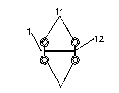
[0036] see Figure 1-Figure 4 , as shown in the legend therein, is an automatic punching fixture for injection molded parts, which is used for punching injection molded parts 1 to form four injection molded products 11 and one injection molded waste 12 .

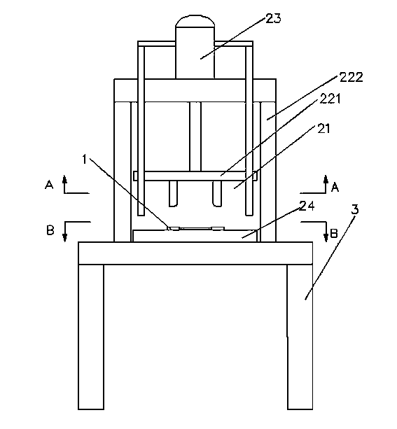
[0037] The above-mentioned automatic punching fixture includes a punching mechanism, a control device (not shown in the figure) for controlling the above-mentioned punching mechanism, and a frame 3 for carrying the above-mentioned punching mechanism and the control device. The mechanism includes a cutter assembly, a punching plate assembly, a punching plate feed cylinder 23 and a support table 24:

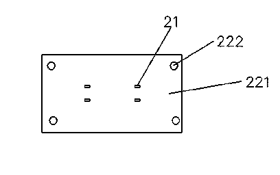
[0038] The cutter assembly includes four punching cutters 21 for punching the injection molded part 1;

[0039] The above punching plate assembly includes a punching plate 221 for fixedly installing the above four punching tools 21 and four punching guide rods 222 for guiding and connecting the punching plates 221;

[0040] The...

Embodiment 2

[0049] see Figure 5 and Figure 6 , as shown in the legend therein, the rest are the same as the embodiment 1, the difference is that the above-mentioned punching mechanism also includes a pressing plate 41 for pressing or releasing the injection molded part 1 and a pressing plate for guiding connection The binder guide hole 42 of 41, the binder guide hole 42 is arranged on the binder plate 41; the punching guide rod 222 is slidably connected in the binder guide hole 42 and is limited to the outlet of the binder guide hole 42; the binder plate 41 There are four hollow parts 411 that allow the punching tool 21 to pass through.

[0050] The following describes the process of using the automatic punching fixture for injection molded parts in this embodiment to punch injection molded parts to form injection products and injection molding waste, including the following steps:

[0051] The first step is to place the injection molded part 1 on the support table 24, and make the in...

Embodiment 3

[0057] see Figure 7 , as shown in the legend therein, the rest are the same as the embodiment 2, the difference is that there is also a press for elastically supporting the punching plate 221 and the pressing plate 41 between the punching plate 221 and the pressing plate 41. The material spring 43 and the pressing material spring 43 are sheathed on the punching guide rod 222 .

[0058] In this embodiment, a pressing spring is added, which can make the relative movement between the punching plate and the pressing plate more moderate, and can realize the reset of the position of the pressing plate.


PUM


Abstract

The invention discloses an automatic punching jig for an injection-molded part, and the automatic punching jig is used for punching the injection-molded part to produce injection-molded products and injection-molded waste. The automatic punching jig comprises a punching mechanism, a control device for controlling the punching mechanism, and a machine frame for bearing the punching mechanism and the control device. The punching mechanism comprises a tool assembly, a punching plate assembly, a punching plate feeding device and a supporting platform, wherein the tool assembly comprises a plurality of punching tools for punching the injection-molded part, the punching plate assembly comprises punching plates for fixation and installation of the plurality of punching tools, and a plurality of punching guiding rods for guiding and being connected with the punching plates respectively, the punching plate feeding device is used for driving the punching plates to slide along the punching guiding rods according to a control instruction of the control device, and the supporting platform is used for bearing the injection-molded part and a discharge hollowed-out portion which allows the injection-molded products to be discharged. According to the automatic punching jig for the injection-molded part, the injection-molded products and the injection-molded waste can obtained in an automated mode in the punching process of the injection-molded part, and the defective percentage of the injection-molded products can be lowered to the largest extent.

Description

technical field [0001] The invention relates to a punching fixture, in particular to an automatic punching fixture for injection molded parts. Background technique [0002] Injection molded parts refer to the collective name of various injection molded products produced by injection molding machines, including various packaging, parts, etc. Since injection molding has the advantages of high production efficiency and easy realization of production automation, injection molding technology is widely used in the production of various packaging parts and parts. Since the products produced by injection molding are not final products, it is necessary to make injection molding parts For processing, the traditional method is to manually cut off unnecessary injection molding waste and leave the required injection molding products. Although injection molding improves production efficiency, manual processing in the later stage takes up a lot of time and reduces the overall production ef...

Claims


Application Information

Patent Timeline
Patent Type & Authority Applications(China)
IPC IPC(8): B26F1/38B26D7/18B26D7/32B29C45/38B29C45/42
Inventor 陈利
Owner 亿和精密工业(威海)有限公司
Why Eureka
Try Eureka