Electronic non-contact bidirectional rotary intelligent wiper motor

A two-way rotating, non-contact technology, applied in electrical components, electromechanical devices, electric components, etc., to achieve the effect of simplifying the structure, low cost, and overcoming the bulky structure

Inactive Publication Date: 2013-12-04
张岳峰 +2
View PDF6 Cites 2 Cited by
  • Summary
  • Abstract
  • Description
  • Claims
  • Application Information

AI Technical Summary

Problems solved by technology

[0003] The technical problem to be solved by the present invention is: to propose an electronic non-contact bidirectional rotating intelligent wiper motor to completely solve the problems caused by the current automobile wiper motor with mechanical contact structure

Method used


Image

  • Electronic non-contact bidirectional rotary intelligent wiper motor
  • Electronic non-contact bidirectional rotary intelligent wiper motor
  • Electronic non-contact bidirectional rotary intelligent wiper motor

Examples


Embodiment Construction

[0019] The present invention will now be described in further detail in conjunction with the accompanying drawings and preferred embodiments. These drawings are all simplified schematic diagrams, which only illustrate the basic structure of the present invention in a schematic manner, so they only show the configurations related to the present invention.

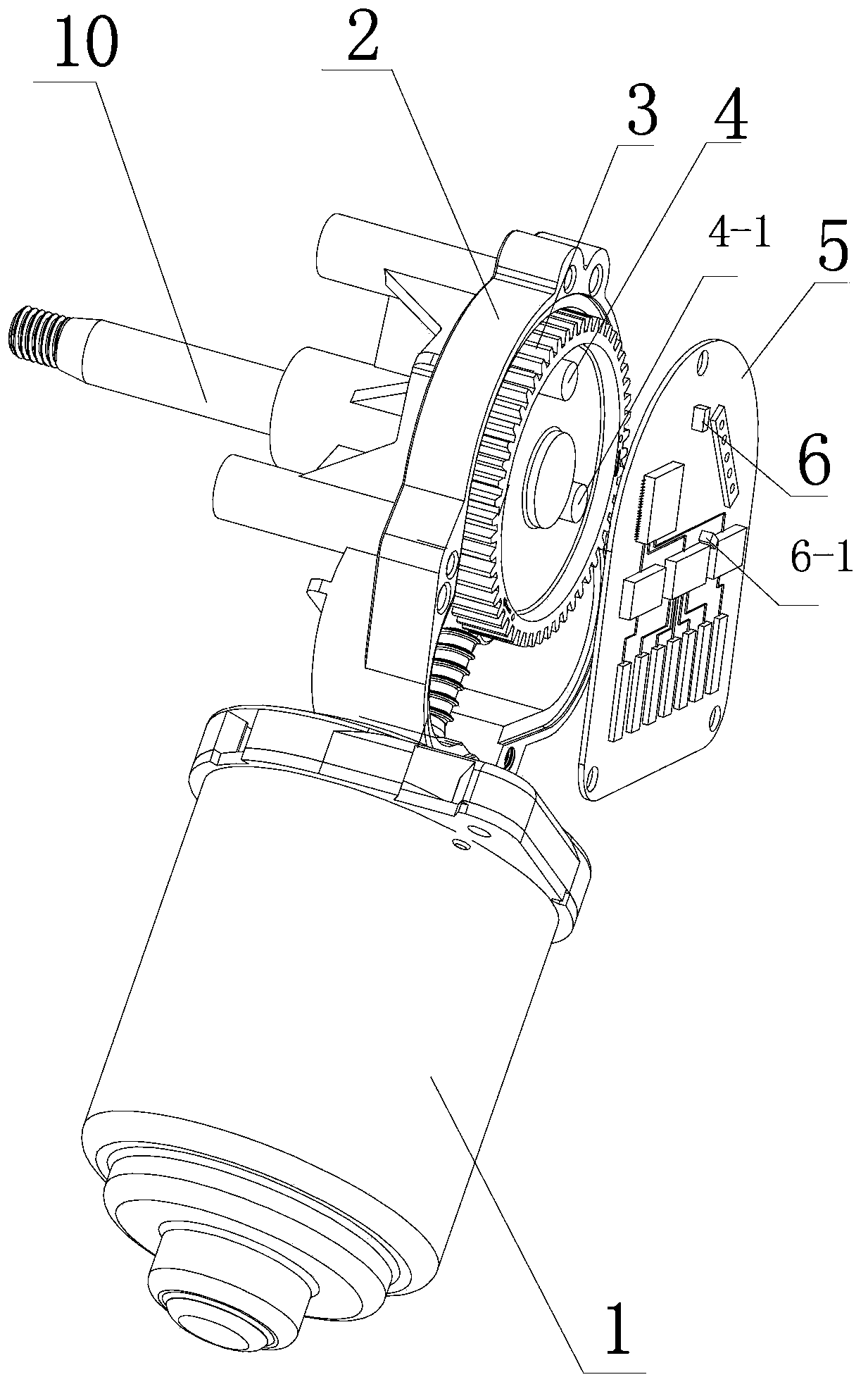
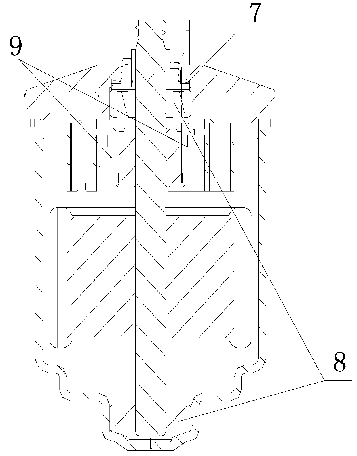
[0020] Such as figure 1 , figure 2 , image 3 , Figure 4 Figure 5 The shown embodiment of an electronic non-contact bidirectional rotating intelligent wiper motor (NIM for short) of the present invention includes a motor body 1, an end cover 2 is arranged on the body 1, and a large gear is arranged inside the end cover 2 3. The large gear is connected with an output shaft 10. The large gear 3 is embedded with an origin positioning magnet 4 and an inflection point positioning magnet 4-1 which rotate together with the large gear 3, and the movement tracks of these two magnets are in the On two different circumferential...


PUM


Abstract

The invention relates to an electronic non-contact bidirectional rotary intelligent wiper motor (called NIM for short) based on a current international and domestic universal mechanical contact motor. The wiper motor overcomes the shortcomings that the mechanical contact motor is cumbersome in structure, short in service life, high in failure rate, unstable in quality, difficult to mount and the like for a long time, interferential radiation cannot be generated when the wiper motor runs, other electronic devices in an automobile are protected from interference, and a structure of a transmission assembly in a wiper assembly is particularly omitted, so that the wiper assembly is simpler in structure and lower in use cost. The wiper motor fills up international and domestic gaps of the field of an automobile wiper motor industry.

Description

technical field [0001] The invention relates to an automobile wiper motor, in particular to an electronic non-contact bidirectional rotating intelligent wiper motor (abbreviated as NIM). Background technique [0002] At present, the wipers used in international and domestic automobiles are all mechanical contacts to form a one-way rotation control structure of the wiper motor and electrical appliances. The disadvantages are: 1. The conversion switch composed of three gears in the first part has a large volume and weight Large, long-term repeated use, large wear, short life, large deformation, complex process, high error rate and failure rate, poor quality stability, difficult installation, especially the left and right swing of the wiper needs to be realized by increasing the transmission rod assembly, resulting in a high cost structure Complicated and other disadvantages. 2. The stop position control composed of three contact pieces and the stop copper plate has large defo...

Claims


Application Information

Patent Timeline
Patent Type & Authority Applications(China)
IPC IPC(8): H02K11/00H02K7/116H02K11/20
Inventor 张岳峰杨雯张小鸣张文明张孟荣王瑛杨林海谷靖金龙周波王洋张孟进
Owner 张岳峰
Why Eureka
Try Eureka