A method for forming a color filter substrate and corresponding spraying device

A color filter, spraying device technology, applied in optics, optical components, nonlinear optics, etc., can solve the problems of difficult scheduling, uneven color, inconsistent spit out, etc., to reduce maintenance time and The steps of cleaning, the effect of improving production efficiency and improving yield

Active Publication Date: 2015-11-25
TCL CHINA STAR OPTOELECTRONICS TECH CO LTD
View PDF2 Cites 0 Cited by
  • Summary
  • Abstract
  • Description
  • Claims
  • Application Information

AI Technical Summary

Problems solved by technology

[0003] However, in this production method, due to the limitations of existing coating methods and coating devices, the problem of uneven color between photoresist layers is likely to occur: because different nozzles are independent mechanical devices, mechanical The difference between the difference and the operation will cause the amount of spit out to be inconsistent, resulting in uneven color
[0004] However, in these existing production methods, for making color filters with different chromaticity (different color filter products) with the same spraying device, if the product is replaced every time, its chromaticity specification generally needs to be changed, At this time, the ink in the spraying device needs to be replaced. First, the pipeline in the nozzle needs to be cleaned before changing the ink, which takes a long time; secondly, it is generally difficult to clean the pipeline in the nozzle. Clean up, so that during the replacement of different ink materials, it is easy to form colloidal coagulation due to the immiscibility of ink materials, which will cause a loss in yield
In addition, the existing production method is not easy to adjust the schedule, thus reducing the production efficiency

Method used


Image

  • A method for forming a color filter substrate and corresponding spraying device
  • A method for forming a color filter substrate and corresponding spraying device
  • A method for forming a color filter substrate and corresponding spraying device

Examples


Embodiment Construction

[0051] Preferred embodiments of the present invention will now be described with reference to the accompanying drawings.

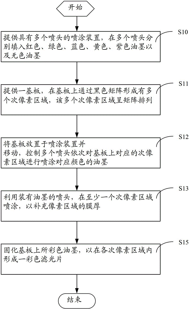
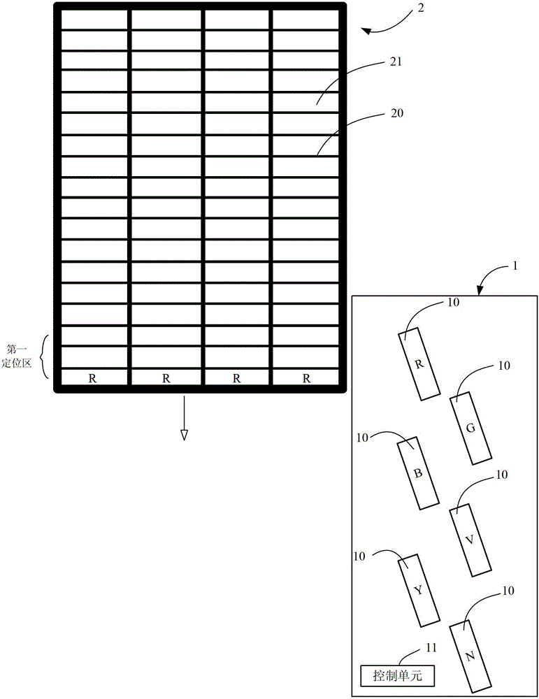
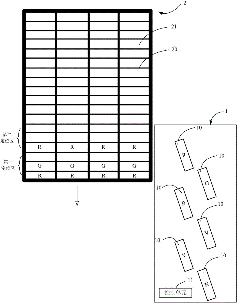
[0052] Such as figure 1 Shown is a schematic diagram of the main flow in an embodiment of a method for forming a color filter substrate provided by the present invention; for ease of understanding, it is combined with figure 2 The schematic diagram in .

[0053] Embodiments of the present invention provide a method for forming a color filter substrate, which includes the following steps:

[0054] Step S10, providing a spraying device 1 with a plurality of nozzles 10, filling the plurality of nozzles 10 with ink of one color, wherein the ink includes red, green, blue, yellow, purple ink and colorless ink, Respectively represented by R, G, B, Y, V and N in the figure;

[0055] Step S11, providing a substrate 2, such as a glass substrate, on which a plurality of sub-pixel regions 21 are formed through a black matrix 20, and the plurality of sub-pixel region...


PUM


Abstract

A method for forming a color filter substrate and a corresponding spraying device. The forming method comprises: providing a spraying device (1) having a plurality of spray heads (10), each spray head being filled with printing ink of one color; providing a substrate (2), and forming a plurality of subpixel regions (21) on the substrate, the plurality of subpixel regions being arranged in a matrix; and placing the substrate on the spraying device and moving same in one direction, and controlling the plurality of spray heads to sequentially spray printing ink of corresponding colors onto corresponding subpixel regions on the substrate once the substrate is moved a fixed distance, at least one row of subpixel regions being sequentially coated with printing ink of different colors. The product qualification rate of manufacturing color filter substrates can be improved, so that the production scheduling is more flexible.

Description

technical field [0001] The invention relates to a thin film transistor liquid crystal display (Thin Film Transistor liquid crystal display, TFT-LCD) manufacturing technology, in particular to a method for forming a color filter substrate and a corresponding spraying device. Background technique [0002] In the new generation of color filter manufacturing technology, especially the inkjet (Ink-Jet Printing, IJP) color filter manufacturing technology that uses nozzles for photoresist coating has advantages. The nozzle (nozzle) coats the photoresist material in the specific pixel of the glass substrate with the black matrix, and only one process can complete the coating of the red, green and blue (RGB) colors of the color filter , using this technology has the advantages of saving equipment, space and materials. [0003] However, in this production method, due to the limitations of existing coating methods and coating devices, the problem of uneven color between photoresist la...

Claims


Application Information

Patent Timeline
Patent Type & Authority Patents(China)
IPC IPC(8): C03C17/00
CPCG02B5/201G02F1/133516
Inventor 陈孝贤
Owner TCL CHINA STAR OPTOELECTRONICS TECH CO LTD
Why Eureka
Try Eureka