Coating device and coating method

A coating device and a coating technology are applied in the coating device and the coating field, which can solve the problems of uneven texture, poor appearance, and uneven film thickness of the coating film, and achieve the effect of reducing the variation of the film thickness

Active Publication Date: 2016-05-18
PANASONIC INTELLECTUAL PROPERTY MANAGEMENT CO LTD
View PDF9 Cites 0 Cited by
  • Summary
  • Abstract
  • Description
  • Claims
  • Application Information

AI Technical Summary

Problems solved by technology

[0019] At this time, the accumulated liquid 119 seeping out on the separator 117 is dragged by the end of the porous member 112, a part of the accumulated liquid 119 moves to the substrate 111, and the film thickness of the coating film on the substrate 111 becomes uneven. And produce unfavorable conditions such as uneven texture
In addition, a part of the liquid accumulation 119 goes back to the back side of the end portion 120 of the separator, that is, the substrate side 121 of the separator, and enters the gap between the separator and the substrate 111 due to capillary action, thereby forming a liquid on the substrate 111. The coating boundary line at the beginning of the coating film on the surface is blurred, resulting in poor appearance

Method used


Image

  • Coating device and coating method
  • Coating device and coating method
  • Coating device and coating method

Examples


Embodiment 1

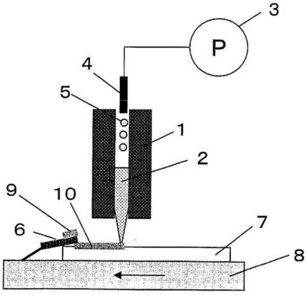
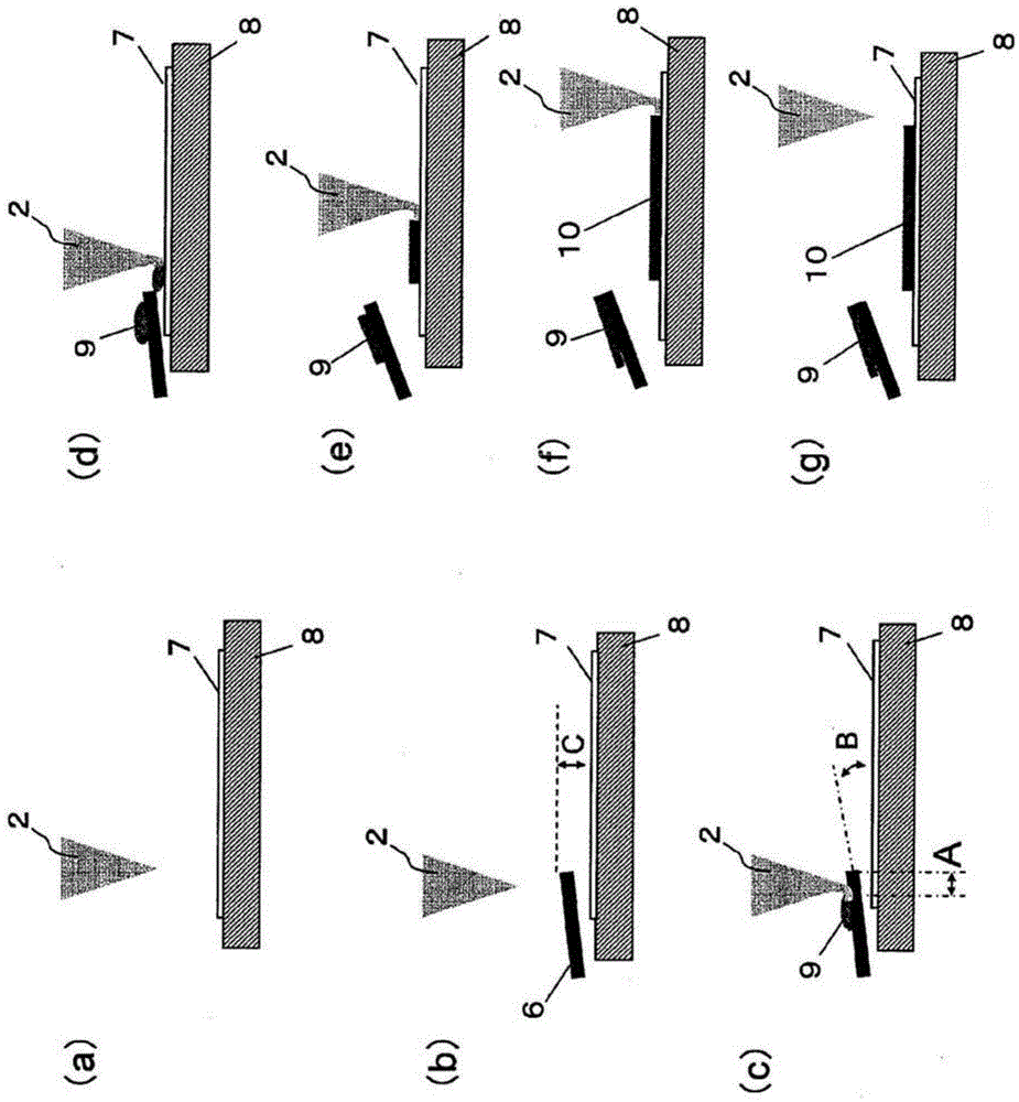
[0065] refer to figure 2 (a)~ figure 2 (g), yes figure 1 The coating operation of the coating device described in .

[0066] First, the substrate 7 is fixed on the transfer table 8 to such an extent that it does not shift due to transfer / coating by a decompression adsorption method, an electrostatic adsorption method, physical fixing, etc., and is moved below the porous member 2. ( figure 2 (a)).

[0067] Next, the spacer 6 is arranged on the coating start position of the substrate 7 ( figure 2 (b)). Then, the distance between the porous member 2 and the separator 6 is reduced by a vertical driving mechanism (not shown) of the porous member 2 , and the end of the porous member 2 is brought into contact with the surface of the separator 6 .

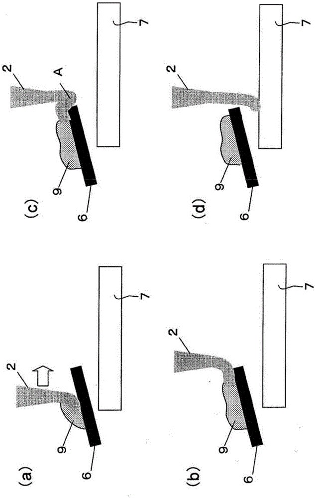
[0068] Here, the coating fluid accumulation 9 occurs at the end of the porous member 2 ( figure 2 (c)). In this state, the porous member 2 and the substrate 7 are relatively moved, and the porous member 2 is moved from the se...

Embodiment 2

[0085] Next, the contents related to the shape of the separator will be described. in the aforementioned image 3 , taking into account the above image 3 (c)~ image 3 In (d), if the end of the porous member 2 is in contact with the substrate 7 in the coating width direction at the same time, air bubbles will be mixed between the end of the porous member 2 and the substrate 7 at a certain position in the width direction. If it is in such a state, it will apply|coat in the state mixed with air bubbles, and coating unevenness may generate|occur|produce.

[0086] This problem can be solved by the apparatus configuration shown below. Figure 5 It is a schematic diagram obtained by observing the positional relationship of the substrate 7 , the end of the porous member 2 , and the separator 6 in a plan view.

[0087] The end of the porous member 2 and the substrate 7 are arranged in a direction perpendicular to the relative movement direction of the end of the porous member 2 a...

Embodiment 3

[0090] Next, the shape of the separator will be described. Figure 6 It is a figure showing the overall shape of a separator. Figure 6 (a) represents a top view, Figure 6 (b) means Figure 6 (a) XX' profile, Figure 6 (c) means Figure 6 (a) YY' profile.

[0091] As described in Examples 1 and 2, the coating liquid oozes out at the position where the end of the porous member 2 is in contact with the separator 6 to generate a fluid accumulation. However, if mass production is considered, each cleaning of the partition plate 6 will increase the loss and cost due to production tact or components and solvents required for cleaning. Therefore, in order to easily remove the accumulated liquid generated on the surface of the separator 6 , a mechanism for removing unnecessary application liquid is provided on the separator 6 . use Figure 6 (a)~ Figure 6 (b) An example thereof will be described.

[0092] At a position closer to the upstream side (opposite to the direction in...


PUM

PropertyMeasurementUnit
viscosityaaaaaaaaaa

Abstract

The invention provides a coating apparatus and a coating method. In contact-type coating of coating by contacting a porous component soaked by a coating liquid to a coating object, non-uniformity is generated on a coating film due to the coating liquid leaked from the porous component. In a contact-type coating device of coating by contacting the porous component soaked by the coating liquid to the coating object, an inclined separator plate is arranged on a starting end of the coating object, so that the coating device has a mechanism for abutting the porous component to the separator plate temporally before the porous component is connected to the coating object and a movable mechanism for enabling the substrate, the separator plate and the porous component to move relatively.

Description

technical field [0001] The present invention relates to a coating device and a coating method for coating a material such as an antireflection film on the surface of a glass substrate for a solar cell or the like. Background technique [0002] At present, a technology for coating solar cells, display panels, lighting devices, etc., is applied to a large area with an anti-reflection film or a functional film called a wavelength adjustment film that blocks light of a specific wavelength. For example, there is diecoating. Figure 9 It is a schematic diagram for explaining the conventional die coating method. [0003] Figure 9 Among them, when coating the functional film on the substrate 111, the coating liquid 114 is discharged from the mold 112' of the longer metal mold in the coating width direction through the slit 113 formed along the length direction of the mold 112', and the coating liquid 114 is deposited on the substrate 111. Apply. At this time, the mold 112' and th...

Claims


Application Information

Patent Timeline
Patent Type & Authority Patents(China)
IPC IPC(8): C03C17/00
Inventor 土田修三堀川晃宏奥村智洋
Owner PANASONIC INTELLECTUAL PROPERTY MANAGEMENT CO LTD
Why Eureka
Try Eureka