Sound source positioning system and method used for distributed microphone arrays

A technology for microphone array and sound source localization, which is applied in the field of sound source localization of microphone arrays, and can solve problems such as large application limitations.

Inactive Publication Date: 2015-04-22
DALIAN UNIV OF TECH
View PDF1 Cites 0 Cited by
  • Summary
  • Abstract
  • Description
  • Claims
  • Application Information

AI Technical Summary

Problems solved by technology

Although this technology is the most widely studied positioning method in the field of array signal processing, it requires that the microphones in the array be arranged linearly at equal intervals, and for distributed arrays with irregular geometric structures, this method is no longer applicable, and this method is mostly applicable to remote Field, narrow-band, stable sound signal, the application limitations are relatively large

Method used


Image

  • Sound source positioning system and method used for distributed microphone arrays
  • Sound source positioning system and method used for distributed microphone arrays
  • Sound source positioning system and method used for distributed microphone arrays

Examples


Embodiment Construction

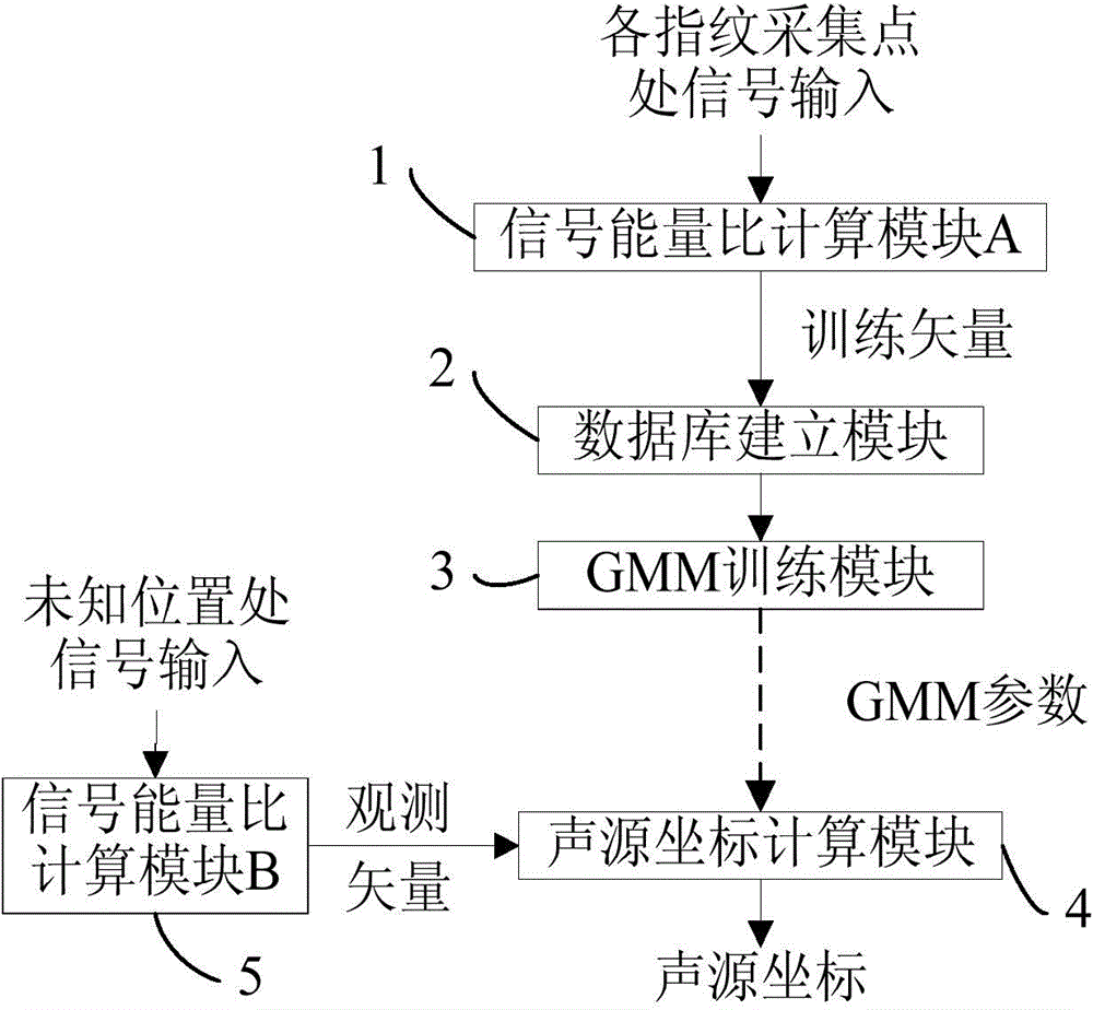
[0076] The present invention will be further described below in conjunction with the accompanying drawings. figure 1 It is a functional block diagram of a sound source localization system based on position fingerprint and GMR. Specific steps are as follows:

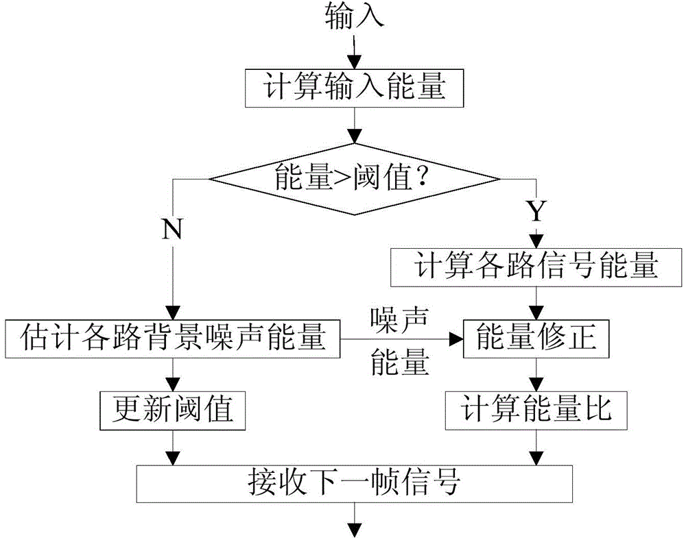
[0077] A. In the deployed microphone array work site, move the sound source to each fingerprint collection point determined in advance, input the collected signal to the signal energy ratio calculation module A, calculate the signal energy ratio, and output the calculation result To the database building module; the signal energy ratio calculation is performed once for each frame signal collected at each fingerprint collection point; the signal energy ratio calculation process is as follows figure 2 shown. The working method of described signal energy ratio calculation module A comprises the following steps:

[0078] First, the validity of the input signal is detected, and the number of microphones in the distributed...


PUM


Abstract

The invention discloses a sound source positioning system and method used for distributed microphone arrays. The system comprises a signal energy ratio calculating module A, a database establishment module, a GMM training module, a signal energy ratio calculating module B and a sound source coordinate calculating module, wherein the output end of the signal energy ratio calculating module A is connected with the input end of the database establishment module, the output end of the database establishment module is connected with the input end of the GMM training module, the output end of the GMM training module is connected with the input end of the sound source coordinate calculating module, the output end of the signal energy ratio calculating module B is also connected with the input end of the sound source coordinate calculating module, and the output end of the sound source coordinate calculating module outputs sound source coordinates. According to the method, due to the fact that a microphone is adopted to receive signal energy to serve as main parameters, the method is only relevant to the distance between the microphone and a sound source, therefore, geometrical structures and size information of the arrays do not need to be considered, and factors such as delay time, stationarity, broadband or narrowband of transmission of sound signals do not need to be considered, either.

Description

technical field [0001] The invention relates to a sound source localization technology of a microphone array, in particular to a sound source localization system and a localization method for a distributed microphone array. Background technique [0002] The microphone array is composed of multiple microphones. Each microphone simultaneously collects and jointly processes the sound signal. While obtaining the time domain and frequency domain information of the signal, it can also obtain the spatial domain (spatial orientation) information of the sound. Using the microphone array and the sound information of the target to obtain the position of the target is an effective localization method. Since the sound picked up by the microphone is a passive detection method, the sound source localization technology based on the microphone array is widely used in military detection, security monitoring, audio / video conference system, human-computer interaction and other fields. [0003]...

Claims


Application Information

Patent Timeline
Patent Type & Authority Patents(China)
IPC IPC(8): G01S5/20
Inventor 陈喆殷福亮王舒文
Owner DALIAN UNIV OF TECH
Why Eureka
Try Eureka