
Separator welding device and separator welding method

一种分离片、熔接的技术,应用在层压装置、化学仪器和方法、连接等方向,能够解决周期变长等问题

Active Publication Date: 2013-12-11
ENVISION AESC JAPAN LTD
View PDF5 Cites 4 Cited by
  • Summary
  • Abstract
  • Description
  • Claims
  • Application Information

AI Technical Summary

Problems solved by technology

[0005] In the technique described in Patent Document 1, since the pressing of the separator and thermal welding are performed in separate steps, there is a problem that the cycle time becomes longer.

Method used


Image

  • Separator welding device and separator welding method
  • Separator welding device and separator welding method
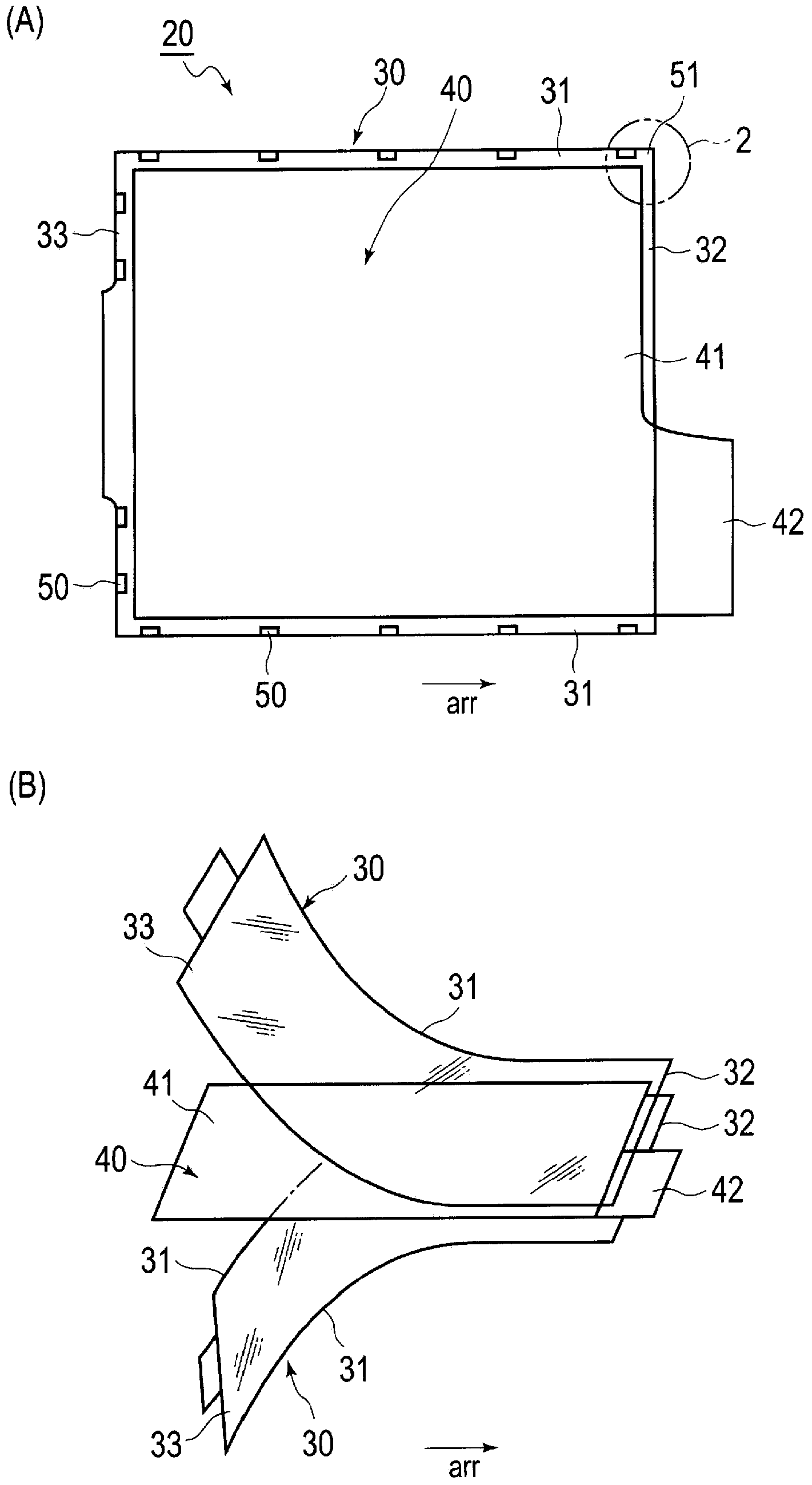
  • Separator welding device and separator welding method

Examples


Embodiment Construction

[0022] Embodiments of the present invention will be described below with reference to the attached drawings. In addition, in description of drawings, the same code|symbol is attached|subjected to the same element, and repeated description is abbreviate|omitted. The dimensional ratios of the drawings are exaggerated for convenience of description and are different from actual ratios.

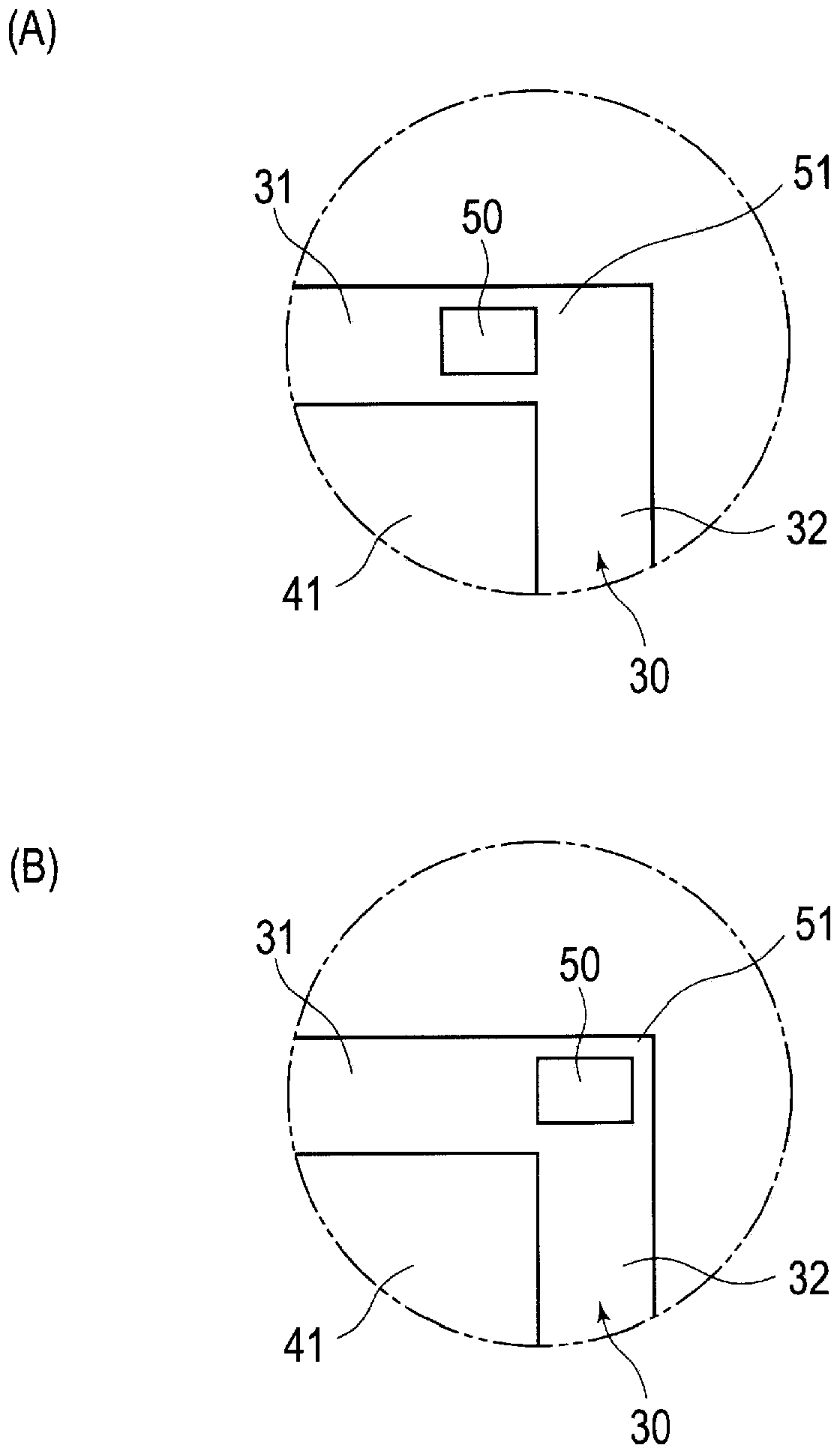
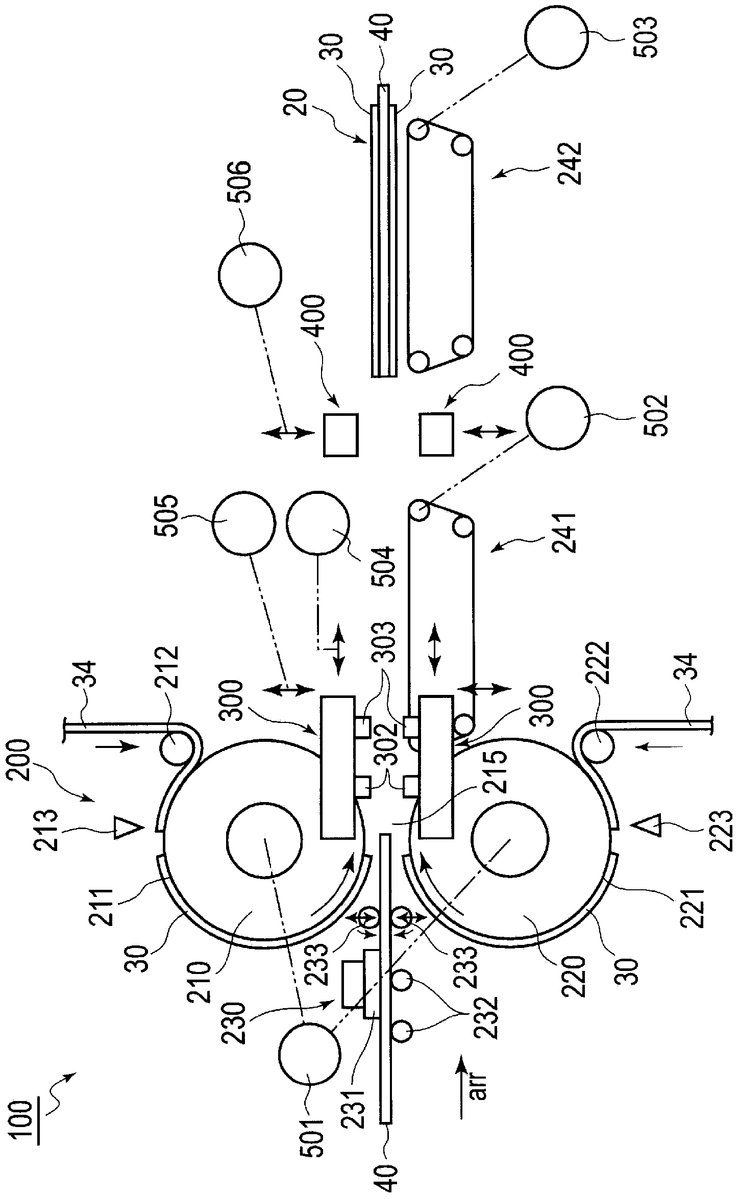
[0023] in addition, figure 1 of (A), figure 1 (B) and image 3 The indicated arrow arr indicates the transport direction in which the electrode 40 and the pair of separators 30 are transported when the bagged electrode 20 is manufactured. exist figure 1 of (A), figure 1 (B) and image 3 In the figure, the right side in the figure is the downstream side of the conveying direction, which is called "front" in each member, and the left side in the figure is the upstream side in the conveying direction, called "rear" in each member. In addition, the edges of the separator in the direction inter...


PUM


Abstract

A device (100) for producing a bagged electrode (20) by applying a separator welding device is provided with a joining head (301). The joining head (301) comprises: joining chips (302, 303) that join a pair of separators (30) to each other; and a restraining unit (304) that restrains the pair of the separators. The joining head (301) is caused to relatively approach the separators, and after the separators are restrained by the restraining unit (304), the separators are joined to each other by the joining chips (302, 303). Meanwhile, the joining head (301) is caused to relatively separate from the separators, and after the joining chips are separated from the pair of the separators, the restraining of the separators by the restraining unit (304) is disengaged.

Description

technical field [0001] The invention relates to a separating sheet welding device and a separating sheet welding method. Background technique [0002] There is known a bagged electrode in which an electrode is bagged between a pair of separators (see Patent Document 1). [0003] In the technique described in Patent Document 1, the positive electrode is placed between separator sheets during bagging, and after the separator is pressed by a pressing member, the outer periphery of the separator is thermally welded by a welding member. [0004] Patent Document 1: Japanese Patent Laid-Open No. 2007-329111 [0005] In the technique described in Patent Document 1, since the pressing of the separator and the thermal welding are performed in separate steps, there is a problem that the cycle becomes long. Contents of the invention [0006] It is an object of the present invention to provide a separator welding device and a separator welding device that can shorten the cycle time r...

Claims


Application Information

Patent Timeline
Patent Type & Authority Applications(China)
IPC IPC(8): H01M2/18H01M4/04H01M50/466
CPCB29L2031/3468B29C65/18B29C65/48B29C65/56B29C65/7894B29C66/8161B29C66/83543B29C65/7847B29C66/1122B29C66/21B29C66/433B29C66/81815B29C66/91421B29C66/93441B29C66/9392B29C65/7852B29K2705/00B32B37/0007B32B37/0053B32B37/0076B32B37/06B32B37/185B32B38/0004B32B38/1833B32B38/1858B32B2309/72B32B2457/10B29C65/7841B29C66/81429B29C65/80H01M10/0585H01M10/0404H01M10/052Y10T29/49204Y02E60/10Y02P70/50H01M50/466H01M10/0468H01M50/46B32B37/0046H01R43/00
Inventor 油原浩柳岳洋山下学
Owner ENVISION AESC JAPAN LTD
Learn More