Core of plate-fin heat exchanger

A technology of plate-fin heat exchangers and cores, which is applied in the direction of heat exchangers, indirect heat exchangers, heat exchange equipment, etc. The problems such as large vibration amplitude of the body can be solved, and the effect of improving mechanical strength, reducing vibration amplitude and increasing welding distance can be achieved.

Inactive Publication Date: 2013-12-25
WUXI YU SHUN HEAT EXCHANGER
View PDF0 Cites 0 Cited by
  • Summary
  • Abstract
  • Description
  • Claims
  • Application Information

AI Technical Summary

Problems solved by technology

The existing seals are relatively short, resulting in low welding connection strength between the seals at the four corners of the core and the heat dissipation pipe, low mechanical strength of the core, and the core is easily damaged due to the large vibration amplitude during operation

Method used


Image

  • Core of plate-fin heat exchanger
  • Core of plate-fin heat exchanger

Examples


Embodiment Construction

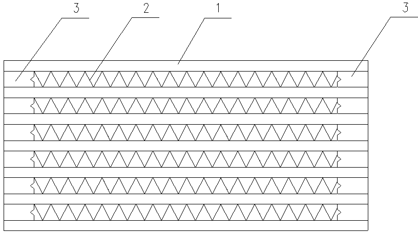
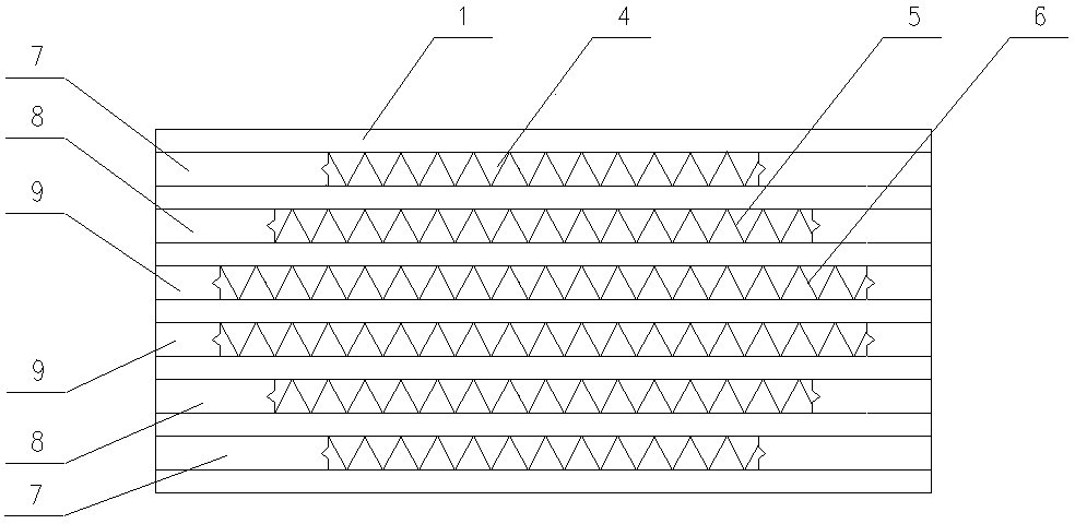
[0010] See figure 2 , the core body of the plate-fin heat exchanger, which includes several cooling tubes 1 and outer fins, the cooling tubes 1 are arranged at intervals, the outer fins are installed between adjacent cooling tubes, and are located in the gap between adjacent cooling tubes Seals are installed at both ends, and the seals are welded and connected to the adjacent heat dissipation pipes. The seals 7, 8, and 9 at the four corners of the core are arranged in a trapezoidal shape, and the length of the seal 7 located outside the core is longer than that located inside the core. The lengths of 8 and 9; the lengths of the seals 7, 8 and 9 at the four corners of the core body are 20mm, 15mm and 10mm from outside to inside. In the figure, 4, 5 and 6 are outer fins with different lengths, wherein the length of the outer fin 6>the length of the outer fin 5>the length of the outer fin 4.


PUM


Abstract

The invention provides a core of a plate-fin heat exchanger. Seal strips and radiating tubes in the core can be welded more intensively, mechanical strength of the core is improved, the vibration amplitude of the core during operating is reduced, and the core rarely damages. The core comprises a plurality of radiating tubes and a plurality of outer fins. The radiating tubes are disposed at intervals. Each outer fin is mounted between the adjacent radiating tubes. Seal strips are mounted at two ends of a gap between the adjacent radiating tubes. The seal strips are connected with the adjacent radiating tubes in a welded manner. The core is characterized in that the seal strips at four corners of the core are arranged in a trapezoidal form, and the seal strips outside the core are longer than those inside the core.

Description

technical field [0001] The invention relates to the technical field of heat exchanger equipment, in particular to a core body of a plate-fin heat exchanger. Background technique [0002] The core body of the existing heat exchanger includes heat dissipation pipes and outer fins, and its structure is as follows: figure 1 As shown, several heat dissipation pipes 1 are distributed at intervals, and the outer fins 2 are installed between adjacent heat dissipation pipes, and seals 3 are installed at both ends of the gap between adjacent heat dissipation pipes, and the seals are welded to the heat dissipation pipes. The existing seals are relatively short, resulting in low welding connection strength between the seals at the four corners of the core and the heat dissipation pipe, low mechanical strength of the core, and the core is easily damaged due to the large vibration amplitude during operation. Contents of the invention [0003] In view of the above problems, the present ...

Claims


Application Information

Patent Timeline
Patent Type & Authority Applications(China)
IPC IPC(8): F28D9/00F28F3/10
Inventor 丁晓江
Owner WUXI YU SHUN HEAT EXCHANGER
Why Eureka
Try Eureka