dc‑dc circuit and its overcurrent protection method

A DC-DC, circuit technology, applied in emergency protection circuit devices, electrical components, regulating electrical variables, etc., can solve problems such as detection current

Inactive Publication Date: 2017-07-28
SHENZHEN TCL NEW-TECH CO LTD
View PDF3 Cites 0 Cited by
  • Summary
  • Abstract
  • Description
  • Claims
  • Application Information

AI Technical Summary

Problems solved by technology

but for figure 2 The DC-DC circuit with an external MOS tube cannot directly detect the current in the upper MOS tube Q21 or the lower MOS tube Q22 through the current detection circuit integrated in the PWM controller

Method used


Image

  • dc‑dc circuit and its overcurrent protection method
  • dc‑dc circuit and its overcurrent protection method
  • dc‑dc circuit and its overcurrent protection method

Examples


Embodiment Construction

[0039] The technical solutions of the present invention will be further described below in conjunction with the accompanying drawings and specific embodiments. It should be understood that the specific embodiments described here are only used to explain the present invention, not to limit the present invention.

[0040] The present invention proposes a DC-DC circuit.

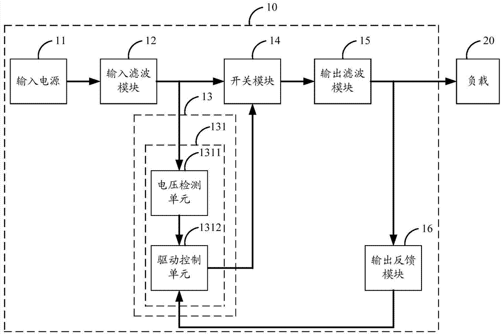
[0041] refer to image 3 , image 3 It is a functional block diagram of a preferred embodiment of the DC-DC circuit of the present invention.

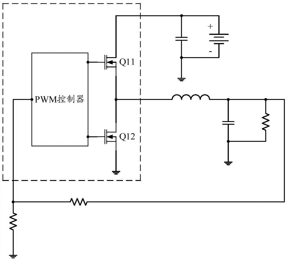
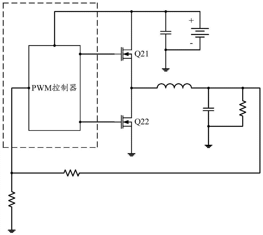
[0042]In a preferred embodiment of the present invention, the DC-DC circuit 10 is connected to the load 20, including an input power source 11, an input filter module 12, a PWM control module 13 and a switch module 14, the PWM control module 13 includes a PWM controller 131, the PWM The controller 131 includes a voltage detection unit 1311 and a driving control unit 1312 .

[0043] The input power supply 11 is respectively connected to the input end of the voltage de...


PUM


Abstract

The invention discloses a DC-DC circuit and an overcurrent protection method thereof. The DC-DC circuit is connected with loads, and comprises an input power supply, an input filtration module, a PWM control module and a switch module, wherein the PWM control module comprises a PWM controller which comprises a voltage detection unit and a drive control unit. In the DC-DC circuit, the input power supply provides input voltages, the alternating components in the switch module generate ripple voltages when flowing through the input filtration module, the voltage detection unit detects the ripple voltages in the input filtration module, the difference value of the input voltages and the ripple voltages is compared with a preset reference voltage, the output of the output currents is controlled according to the comparative results, therefore, detection on the output currents can be achieved by detecting the ripple voltages, so that when overcurrent occurs to the DC-DC circuit, the output of the currents is cut off, and the purpose of overcurrent protection is achieved.

Description

technical field [0001] The invention relates to the technical field of power supplies, in particular to a DC-DC circuit and an overcurrent protection method thereof. Background technique [0002] Currently, DC-DC circuits with buck topology are widely used in the electronics industry. The common BUCK topology DC-DC circuit has two specific forms: one is that the PWM controller is integrated with the MOS tube (or the PWM controller is only integrated with the MOS tube), such as figure 1 As shown; the other is that the PWM controller does not integrate MOS tubes at all, and needs to use two MOS tubes outside the PWM controller, such as figure 2 shown. [0003] for figure 1 For the current overcurrent protection of the DC-DC circuit, the designer often integrates a current detection circuit inside the PWM controller, through which the current detection circuit directly detects the current flowing between the drain and the source of the upper MOS transistor Q11 or the lower ...

Claims


Application Information

Patent Timeline
Patent Type & Authority Patents(China)
IPC IPC(8): H02M3/155H02H7/12
Inventor 贺顺亮
Owner SHENZHEN TCL NEW-TECH CO LTD
Why Eureka
Try Eureka