pwm drive circuit

A driving circuit and driving end technology, applied in circuit devices, emergency protection circuit devices, electrical components, etc., can solve problems such as high power consumption, limitation of overall circuit response speed, and large area occupied by comparators

Active Publication Date: 2017-08-08
SHENZHEN SKYWORTH RGB ELECTRONICS CO LTD
View PDF6 Cites 0 Cited by
  • Summary
  • Abstract
  • Description
  • Claims
  • Application Information

AI Technical Summary

Problems solved by technology

However, this overcurrent protection scheme has the following disadvantages: first, the current must be detected through a sampling resistor, and the resistance is easily affected by factors such as process and temperature, and the sampling accuracy cannot be guaranteed; second, one or more high-resolution The comparator is used for voltage comparison. The comparator occupies a large area, and the response speed of the overall circuit is also limited by the comparator. Big

Method used


Image

  • pwm drive circuit
  • pwm drive circuit

Examples


Embodiment Construction

[0035] The technical solutions of the present invention will be further described below in conjunction with the accompanying drawings and specific embodiments. It should be understood that the specific embodiments described here are only used to explain the present invention, not to limit the present invention.

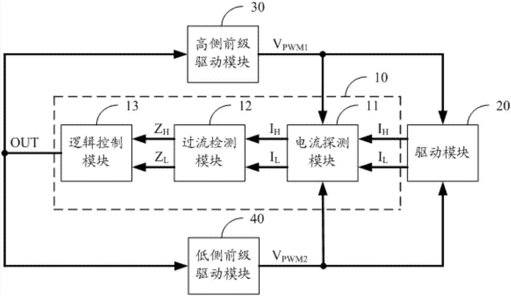
[0036] refer to figure 1 , figure 1 It is a functional block diagram of a preferred embodiment of the PWM driving circuit of the present invention.

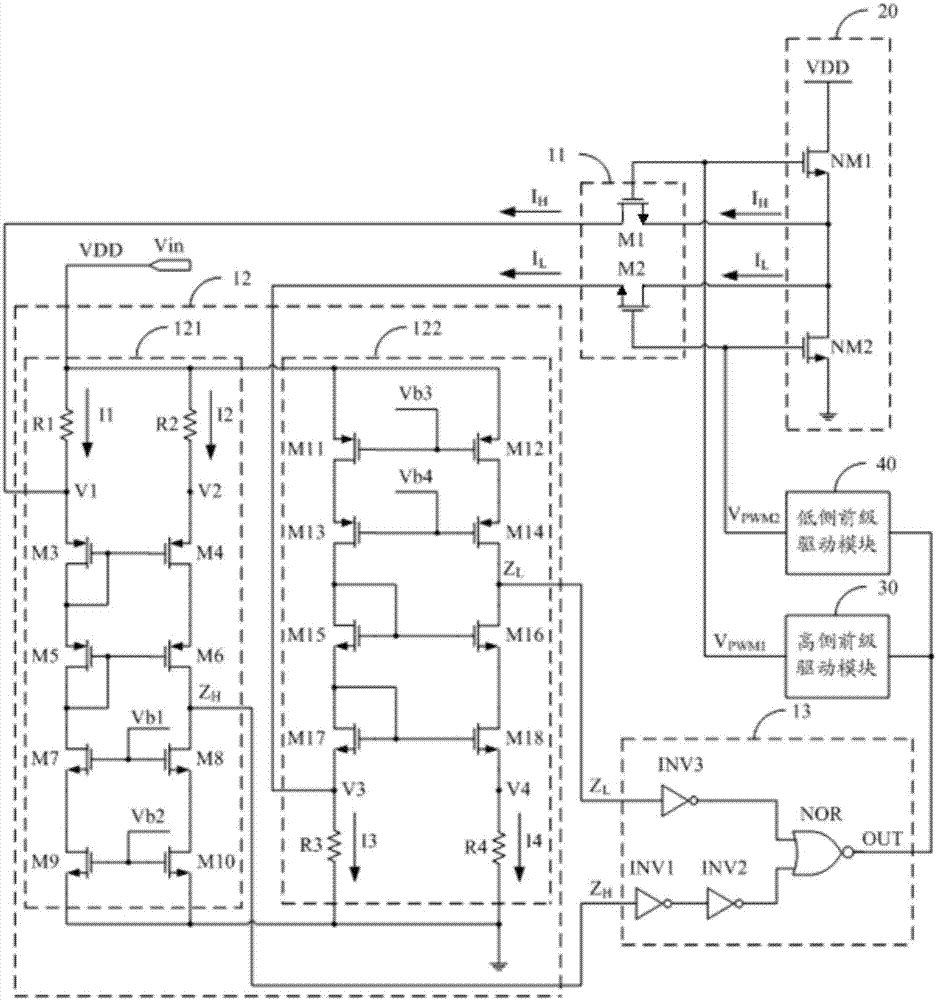
[0037] A preferred embodiment of the present invention provides a PWM drive circuit, the PWM drive circuit includes an overcurrent protection circuit 10, a drive module 20, a high-side pre-stage drive module 30 and a low-side pre-stage drive module 40, the overcurrent protection circuit 10 Connect to the drive module 20, the high-side front-end drive module 30 and the low-side front-end drive module 40 respectively, detect the high-side drive current and the low-side drive current in the drive module 20 in real time, s...


PUM


Abstract

The invention discloses a PWM drive circuit. The PWM drive circuit includes a drive module, a high-side pre-drive module, a low-side pre-drive module and an overcurrent protection circuit. The overcurrent protection circuit includes a current detection module and an overcurrent detection module. and logic control module. In the present invention, the high-side driving current and the low-side driving current in the driving module are detected in real time by the current detection module, and the high-side detection current and the low-side detection current are obtained. The high-side detection current of the overcurrent detection module is greater than the high-side setting value. When the high-side level of the output is inverted and / or the low-side detection current is greater than the low-side set value, the output low-side level is inverted, and the high-side level and / or the low-side level is inverted by the logic control module When the overcurrent protection signal is output to achieve the purpose of overcurrent protection, the sampling accuracy of the current is improved, the effective overcurrent protection of the PWM drive circuit is realized, and the circuit power consumption and design cost are reduced at the same time.

Description

technical field [0001] The present invention relates to the technical field of integrated circuit design, in particular to a PWM (Pulse Width Modulation, pulse width modulation) drive circuit. Background technique [0002] Almost all electronic systems specify the rated current, and the current under normal working conditions is not allowed to exceed the rated current, otherwise the load or internal components of the system will be burned. Qualified integrated circuits or electronic products must take over-current protection measures, which is an important indicator to verify product reliability. [0003] The working mode of the existing overcurrent protection circuit is basically to sample the current flowing through the circuit load through the sampling resistor, and then convert the sampled current into a voltage, compare it with the preset voltage value through a comparator, and output The corresponding control signal realizes the over-current protection function. Howe...

Claims


Application Information

Patent Timeline
Patent Type & Authority Patents(China)
IPC IPC(8): H02H3/087
Inventor 孙天奇姚森宝吴冰洁邵彦生
Owner SHENZHEN SKYWORTH RGB ELECTRONICS CO LTD
Why Eureka
Try Eureka