Direct current control circuit

A technology of DC control circuit and drive circuit, applied in the field of electronics, can solve problems such as failure of short-circuit protection, achieve effective short-circuit, and avoid the effect of starting blanking time

Inactive Publication Date: 2018-08-17
湖州市菱湖兴菱电力电子厂
View PDF1 Cites 0 Cited by
  • Summary
  • Abstract
  • Description
  • Claims
  • Application Information

AI Technical Summary

Problems solved by technology

However, there is a protection blind zone for the start-up blanking time in the short-circuit protection circuit (undersaturation detection circuit) popular in the market. When the switch is turned on during this time, the short-circuit protection will fail.

Method used


Image

  • Direct current control circuit
  • Direct current control circuit

Examples


Embodiment Construction

[0013] The technical solutions in the embodiments of the invention will be clearly and completely described below in conjunction with the accompanying drawings in the embodiments of the invention. Obviously, the described embodiments are only part of the embodiments of the invention, not all of them. Based on the embodiments of the invention, all other embodiments obtained by persons of ordinary skill in the art without creative efforts belong to the protection scope of the invention.

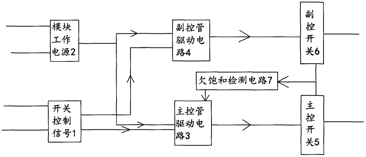
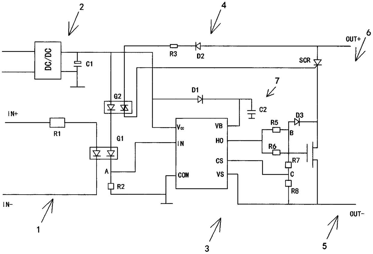
[0014] like figure 1 and 2 As shown, the DC control circuit includes an input terminal connected to the switch control signal 1 and a module working power supply 2, the module working power supply is respectively connected to the main control control drive circuit 3 and the auxiliary control control drive circuit 4, and the switch control signal is respectively connected to the main control control drive circuit 4. Control control drive circuit and auxiliary control drive circuit, the main con...


PUM


Abstract

The invention relates to the technical field of electrons, and relates to a novel control circuit, in particular to a direct current control circuit. The direct current control circuit comprises an input end connected with a switch control signal and a module working power supply; the module working power supply is respectively connected to a main control management driving circuit and an auxiliary control management driving circuit; the switch control signal is respectively connected to the main control management driving circuit and the auxiliary control management driving circuit; the maincontrol management driving circuit is connected with a main control switch; and the auxiliary control management driving circuit is connected with an auxiliary control switch. The direct current control circuit has the advantages that the direct current control circuit adopts a figure of combining the main control switch with the auxiliary control switch into one master switch; and by respectivelyand sequentially starting the main control switch and the auxiliary control switch, when the master switch is turned on, start blanking time of the driving circuits is avoided, and the master switchis totally conducted in a detection monitoring state of the driving circuits, so that short circuit and overcurrent protection can be more effectively carried out.

Description

technical field [0001] The invention relates to the field of electronic technology, and refers to a control circuit, especially a DC control circuit. Background technique [0002] The control circuit can be a non-contact switch composed of microelectronic circuits, discrete electronic devices, and power electronic power devices. Isolation device is used to realize the isolation of control terminal and load terminal. The input terminal of some control circuits uses tiny control signals to directly drive high-current loads. [0003] Some control circuits are a new type of non-contact switching device composed entirely of solid-state electronic components. It uses the switching characteristics of electronic components (such as switching transistors, bidirectional thyristors and other semiconductor devices) to achieve non-contact and sparkless grounding. The purpose of making and breaking the circuit, so it is also called "non-contact switch". It can be seen from the above th...

Claims


Application Information

Patent Timeline
Patent Type & Authority Applications(China)
IPC IPC(8): H03K17/082H03K17/06H03K17/60H03K17/72
CPCH03K17/0824H03K17/06H03K17/0826H03K17/60H03K17/72
Inventor 宋宏明孔安澜
Owner 湖州市菱湖兴菱电力电子厂
Why Eureka
Try Eureka