Cable holder

The technology of a wire gripper and a wire gripping plate is applied in the direction of the device that can bend the lead wire, the bundling material, the parts of the bundling machine, etc.

Inactive Publication Date: 2014-01-01
国网山东省电力公司临清市供电公司
View PDF4 Cites 0 Cited by
  • Summary
  • Abstract
  • Description
  • Claims
  • Application Information

AI Technical Summary

Problems solved by technology

[0002] Existing wired devices, such as mice, earphones, chargers, etc., all have long cables, which are easy to be tangled into a mess when carrying and storing, and it is troublesome to organize

Method used


Image

  • Cable holder
  • Cable holder
  • Cable holder

Examples


Embodiment 1)

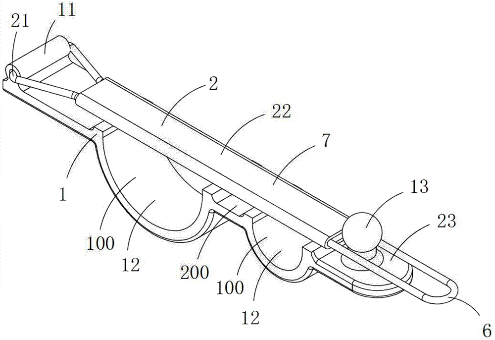
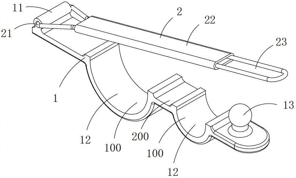
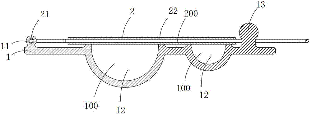
[0015] Figure 1 to Figure 5 A first embodiment of the invention is shown in which, figure 1 It is a schematic diagram of a three-dimensional structure when the first structure of the present invention is in a closed state; figure 2 yes figure 1 A schematic diagram of a three-dimensional structure of the tensioner shown when it is in an open state; image 3 yes figure 1 A front view of the tensioner shown; Figure 4 yes figure 1 A schematic diagram of a three-dimensional structure of the sealing plate in the clamp shown; Figure 5 yes figure 1 An application diagram of the tensioner shown.

[0016] The present embodiment is a kind of clamp, see Figure 1 to Figure 3 As shown, the clamp 4 includes a clamping plate 1 and a sealing plate 2; one end of the sealing plate is rotatably connected to the clamping plate, and the other end is detachably connected to the clamping plate; one end of the clamping plate is provided with a rotating connection 11. There are two semici...

Embodiment 2)

[0021] Figure 6 to Figure 8 A second embodiment of the invention is shown, in which Figure 6 It is a schematic diagram of a three-dimensional structure of the second structure of the present invention; Figure 7 yes Figure 6 A schematic diagram of a three-dimensional structure of the sealing plate in the clamp shown; Figure 8 yes Figure 7 An exploded view of the cover plate shown.

[0022] This embodiment is basically the same as Embodiment 1, the difference is: see Figure 6 to Figure 8 As shown, the sealing plate 2 includes a cross-shaped rod 6 made of steel wire and a stopper 8 arranged in the middle of the cross-shaped rod, and a gap 62 is provided on one side of the middle part of the cross-shaped rod 6; the stopper 8 There is a sleeve hole 81 at the center of the end plate body on one side, and the end plate body on the other side first extends outward and then rolls up to form a U-shaped chute 82. The opening of the U-shaped chute 82 is located at the middle e...


PUM


Abstract

The invention discloses a cable holder which comprises a cable holding plate and a closure plate. One end of the closure plate is connected with the cable holding plate in a rotating mode, and the other end of the closure plate is detachably connected with the cable holding plate; a rotating connection portion is arranged at one end of the cable holding plate, two grooves are formed in the middle of the cable holding plate, and a protruding spherical clamping bead is arranged at the other end of the cable holding plate; the closure plate comprises a connection portion used for being matched with the rotating connection portion of the cable holding plate, blocking portions used for covering the grooves in the cable holding plate in a sealed mode, and a clamping hole used for being connected with the spherical clamping bead in a clamped mode. When the spherical clamping bead is connected in the clamping hole in the clamped mode, the blocking portions and the grooves are enclosed and form two holding holes. The cable holder enables cables to be bundled up tidily and is easy to use.

Description

technical field [0001] The invention belongs to the technical field of clamping tools. Background technique [0002] Existing wired devices, such as mice, earphones, chargers, etc., all have long cables, which cause them to be easily tangled into a mess when carrying and storing, and it is troublesome to organize. Contents of the invention [0003] The object of the present invention is to provide a wire clamp that can bundle cables neatly and is easy to use. [0004] The technical solution to achieve the purpose of the present invention is: a thread clamp, including a thread clamp and a sealing plate; one end of the sealing plate is connected to the thread clamp in rotation, and the other end is detachably connected to the thread clamp; one end of the thread clamp is There is a rotating connection part, two grooves in the middle, and a protruding spherical snap bead at the other end; the sealing plate includes a connecting part for matching with the rotating connection p...

Claims


Application Information

Patent Timeline
IPC IPC(8): H01R13/72F16L3/10
CPCB65B13/02B65B13/18
Inventor 黄海林
Owner 国网山东省电力公司临清市供电公司
Why Eureka
Try Eureka