Method and device for calibrating four-optical-axis return and gas bath type linear displacement laser interferometer

A laser interferometer and laser interference technology, applied in the direction of using optical devices, measuring devices, instruments, etc., can solve the problem of large Abbe error, inaccurate calibration measurement results, and inability to determine whether the interferometric mirror group and the measuring mirror belong to standard laser interference. The parts of the instrument are still calibrated, etc., to achieve the effect of small Abbe error.

Active Publication Date: 2015-03-11
HARBIN INST OF TECH
View PDF2 Cites 0 Cited by
  • Summary
  • Abstract
  • Description
  • Claims
  • Application Information

AI Technical Summary

Problems solved by technology

Since the two sets of laser interferometers are placed in parallel, the two paths of light are similarly affected by the environment, and the refractive index of air has little influence on the two paths of light. Big error
[0004] figure 2 It is a schematic diagram of the face-to-face laser interferometer calibration device. The standard measuring mirror and the calibrated measuring mirror are installed on the moving platform face to face. The advantage is that the measuring beam axes of the two sets of laser interferometers can be adjusted to almost the same measuring axis. The Abbe error is very small. The disadvantage is that the near end of one interferometer is the far end of the other.
[0005] In 2011, the National Institute of Metrology established the first 80-meter long-length laser interferometer measurement device in China (Leng Yuguo, Tao Lei, Xu Jian. Analysis of the accuracy and influencing factors of the dual-frequency laser interferometer system based on the 80-meter measurement device. Metrology and Testing Technology, 2011, 38(9): 47-49), the standard device used is to place three Agilent5530 long-distance dual-frequency laser interferometers in parallel to form a three-way laser interferometer, and the calibrated laser interferometer The instrument is placed between them for calibration and calibration. This scheme is a derivative of the parallel calibration method, and since three-way light is used for simultaneous measurement, it can compensate for the Abbe error during measurement. However, since three lasers are placed in parallel Therefore, the spatial position of the three-way standard measurement light is relatively far away, and the distance between the measurement light of the calibrated laser interferometer and each standard measurement light is also relatively long. All measurement light paths are affected by the environment differently, and the air refractive index has inconsistent effects on all measurement light paths. , resulting in inaccurate calibration measurements
Since the two sets of laser interferometers share one interferometer group and measuring mirror, it is impossible to determine whether the shared interferometer group and measuring mirror belong to the standard laser interferometer part or the calibrated standard laser interferometer part. Therefore, it is not exactly two sets Calibration of the laser interferometer for calibration

Method used


Image

  • Method and device for calibrating four-optical-axis return and gas bath type linear displacement laser interferometer
  • Method and device for calibrating four-optical-axis return and gas bath type linear displacement laser interferometer
  • Method and device for calibrating four-optical-axis return and gas bath type linear displacement laser interferometer

Examples


Embodiment Construction

[0029] The specific embodiments of the present invention will be further described in detail below in conjunction with the accompanying drawings.

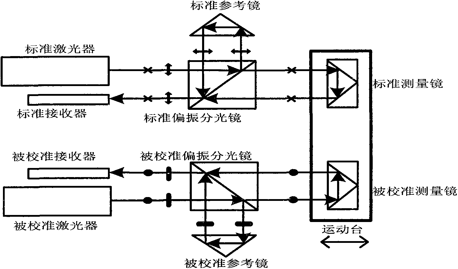
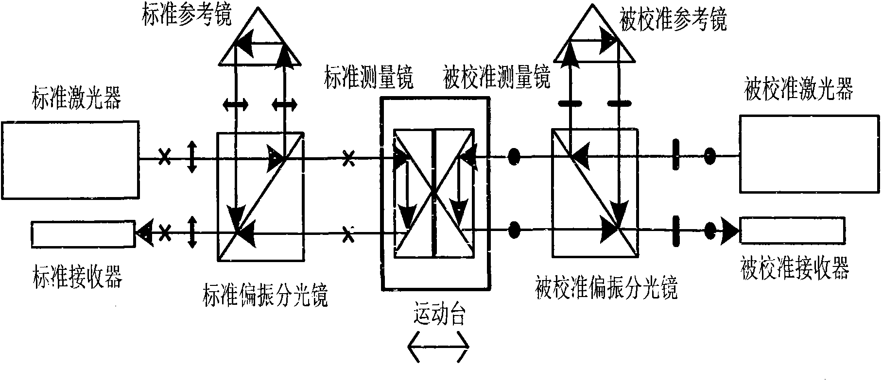
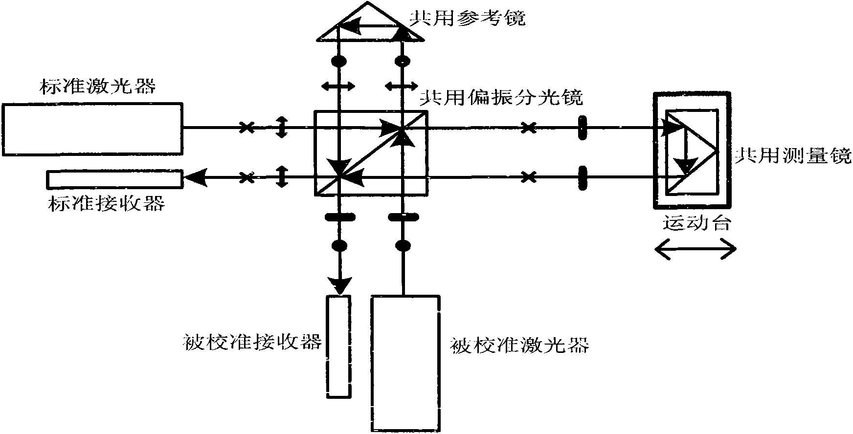
[0030] A four optical axis return and air bath linear displacement laser interferometer calibration device, including a standard laser interferometer laser 1 and four receivers 8, 9, 10, 11. The wires connect the four receivers 8, 9, 10, 11 to the standard laser interferometer signal processing system 12 respectively; the middle through hole 16 is arranged on the output optical path of the standard laser interferometer laser 1 to allow the calibrated laser to interfere The four-axis hollow standard laser interferometer group 2 through which the instrument measuring beam 15 passes; the guide rail 22 is arranged on one side of the four-axis hollow standard laser interferometer group 2, and the moving table 21 is fitted on the guide rail 22, and the moving table 21 passes through the micro-movement The device 20 is equipped with a pla...


PUM


Abstract

The invention relates to a method and a device for calibrating a four-optical-axis return and gas bath type linear displacement laser interferometer and belongs to a laser measurement technology. According to the invention, a measurement beam of the calibrated laser interferometer passes through a middle through hole of a four-axis hollow laser interference mirror set and the measurement beam of the calibrated laser interferometer is placed in parallel at the middle position among four parallel standard measurement beams which are distributed in a side edge form of a regular quadrangular prism; vertical distances between the standard measurement beams and the measurement beam of the calibrated laser interferometer are very small and the average value of the air refractive indexes of the four standard measurement beams is approximate to the value of the air refractive index of the measurement beam of the calibrated laser interferometer; a stable gas bath environment formed by a gas bath device enables the average value of the air refractive indexes of the four standard measurement beams to be more approximate to the value of the air refractive index of the measurement beam of the calibrated laser interferometer; and microinching equipment is used for carrying out real-time return compensation on a target reflector according to an average value of derivative displacements measured by four beam position detectors so as to ensure that the incidence position of the measurement beam on the reflecting surface of the target reflector is not changed.

Description

technical field [0001] The invention belongs to the technical field of laser measurement, and mainly relates to a laser interferometer calibration method and device. Background technique [0002] Laser interferometry linear displacement technology is a standard measurement technology with high precision. It is widely used in precision and ultra-precision machining, microelectronics equipment, nanotechnology industrial equipment and national defense equipment. In order to ensure the accuracy of laser interferometer measurement of linear displacement , requires a scientific and effective linear displacement laser interferometer calibration method and device. The general idea of ​​calibrating a linear displacement laser interferometer is to use a linear displacement laser interferometer with a higher level of precision for calibration. When the accuracy of the two is similar, it is called comparison. In the actual calibration work, most of the linear displacement laser interfe...

Claims


Application Information

Patent Timeline
Patent Type & Authority Patents(China)
IPC IPC(8): G01B9/02G01B11/02
Inventor 谭久彬胡鹏程毛帅
Owner HARBIN INST OF TECH
Why Eureka
Try Eureka