Synchronous telescopic electric soldering iron heat dissipation frame

A technology of electric soldering iron and heat sink, which is applied to soldering irons, auxiliary devices, metal processing equipment, etc., can solve the problems of easy oxidation of soldering iron tips, waste of energy, and short time.

Active Publication Date: 2014-01-22
启东市富晨天然气有限公司
View PDF4 Cites 4 Cited by
  • Summary
  • Abstract
  • Description
  • Claims
  • Application Information

AI Technical Summary

Problems solved by technology

[0002] At present, although the adjustable constant temperature electric soldering irons on the market can control the working temperature range of the electric soldering iron, it is unavoidable to place the electric soldering iron temporarily due to the board circuit or personnel relationship during the use

Method used


Image

  • Synchronous telescopic electric soldering iron heat dissipation frame
  • Synchronous telescopic electric soldering iron heat dissipation frame
  • Synchronous telescopic electric soldering iron heat dissipation frame

Examples


Embodiment Construction

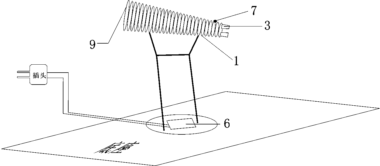
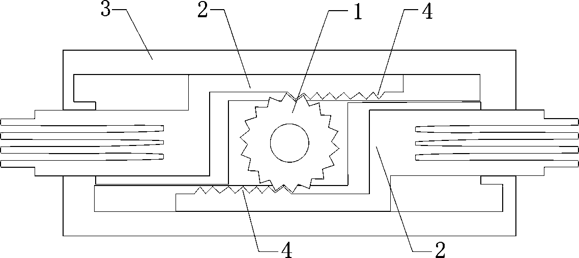
[0024] The present invention is a synchronous telescopic electric soldering iron cooling frame, which is composed of stepping motor 1, heat dissipation block 2, main body 3, tooth row 4, resistor 5, control module 6, sensor 7, diode 8 and sleeve 9.

[0025] exist figure 1 Among them, the soldering iron stand is connected with the sleeve 9 by means of a support rod, a sensor 7 is designed above the end of the sleeve 9, the main body 3 is installed at the tail, and the control module 6 is installed in the middle of the support rod above the soldering iron stand, and the control module 6 leads to a power supply plug.

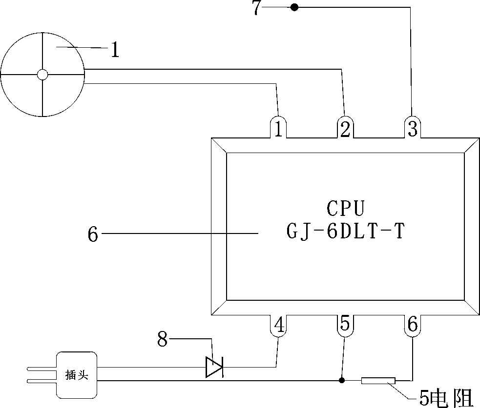
[0026] exist figure 2 Among them, the No. 1 and No. 2 pins of the control module 6 are connected to the stepper motor 1, the No. 3 pin is connected to the sensor 7, the No. 4 pin is connected to one end of the power plug by means of a diode 8, and the other end of the power plug is connected to the No. 5 pin. Connection, a resistor 5 is connected in series betwe...


PUM


Abstract

The invention discloses a synchronous telescopic electric soldering iron heat dissipation frame. The synchronous telescopic electric soldering iron heat dissipation frame is composed of a step motor, heat dissipation blocks, a main body, a toothrow, a resistor, a control module, a sensor, a diode and a sleeve and is characterized in that electric soldering iron is connected with the sleeve through a supporting rod, the sensor is designed above the tail end of the sleeve, the main body is arranged at the tail portion of the sleeve, the left side and the right side in the main body are respectively provided with one heat dissipation block, the step motor is installed in the middle of the main body, and a gear of the step motor corresponds to the toothrow. A first foot and a second foot of the control module are connected with the step motor, a third foot is connected with the sensor, and a fourth foot is connected with one end of a power plug through the diode. The other end of the power plug is connected with a fifth foot, and the resistor is connected between the fifth foot and a sixth foot in series. The synchronous telescopic electric soldering iron heat dissipation frame has the function of changing the contact area between the heat dissipation blocks and the air according to different temperatures of a soldering head so as to dissipate heat of different heat conduction area.

Description

technical field [0001] The invention relates to the temperature control technology of the electric soldering iron when it is in use, and specifically relates to a synchronous telescopic electric soldering iron cooling frame. Background technique [0002] At present, although the adjustable constant temperature electric soldering irons on the market can control the working temperature range of the electric soldering iron, it is unavoidable to place the electric soldering iron temporarily due to the board circuit or personnel relationship during the use of the electric soldering iron. Short-lived, that is, the dormant state. At this time, although the electric soldering iron is in the set constant temperature state, due to the relatively concentrated heat, the soldering iron tip is easy to oxidize, and at the same time, it also causes a waste of energy. Contents of the invention [0003] The object of the present invention is to provide a synchronously telescopic electric s...

Claims


Application Information

Patent Timeline
IPC IPC(8): B23K3/08B23K3/03
CPCB23K3/027B23K3/085
Inventor 庄景阳
Owner 启东市富晨天然气有限公司
Why Eureka
Try Eureka