3D (three dimensional) film and television system and 3D projection method

A 3D, film and television technology, applied in the field of optics, can solve the problems of dim and blurred images, poor visual effects, small ratio, etc., and achieve good visual effects and bright and clear images

Active Publication Date: 2014-01-22
BEIJING AIGEXINDA TECH CO LTD
View PDF4 Cites 8 Cited by
  • Summary
  • Abstract
  • Description
  • Claims
  • Application Information

AI Technical Summary

Problems solved by technology

[0004] In such a 3D video system, since the projection light of the projector passes through the transmissive polarizer 1, reflection and transmission occur, only the transmitted light reaches the first liquid crystal wave plate group 2, and then reaches the s

Method used


Image

  • 3D (three dimensional) film and television system and 3D projection method
  • 3D (three dimensional) film and television system and 3D projection method

Examples


Example Embodiment

[0020] The present invention will be further described in detail below through specific embodiments and in conjunction with the accompanying drawings.

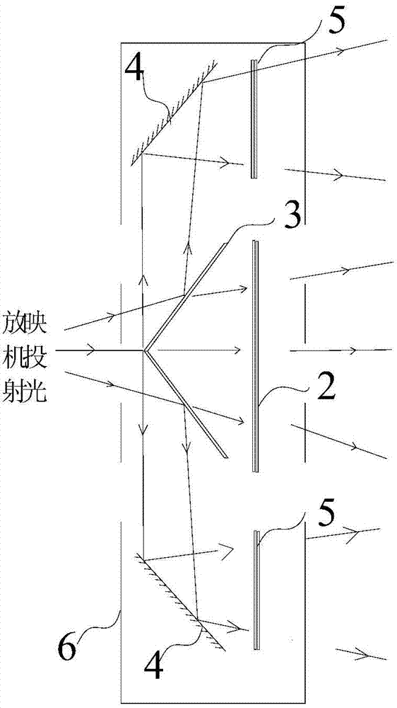
[0021] In the embodiment of the present invention, a 3D video system is provided, such as figure 2 As shown, an L-shaped reflective polarizer 3, two mirrors 4, a first liquid crystal wave plate group 2 and two second liquid crystal wave plate groups are used to divide the incident projection light into transmitted light and two reflected light beams. 5; the transmission direction of the L-shaped reflective polarizer 3 is provided with a first liquid crystal wave plate group 2; the reflection direction of each beam of reflected light of the L-shaped reflective polarizer 3 is provided with a second liquid crystal wave for reflecting the reflected light to the second liquid crystal wave. The mirror 4 of the plate group 5; the reflection direction of the mirror 4 is provided with a second liquid crystal wave plate group 5; the li...


PUM


Abstract

The invention relates to the field of optics, in particular to a 3D film and television system and a 3D film and television method. The 3D film and television system comprises an L-shaped reflection type polaroid, two reflection mirrors, a first liquid crystal wave plate set and two second liquid crystal wave plate sets, wherein the L-shaped reflection type polaroid is used for splitting incident projection light into transmission light and two beams of reflection light; the first liquid crystal wave plate set is arranged in a transmission direction of the L-shaped reflection type polaroid; a reflection mirror which is used for reflecting the reflection light to a second liquid crystal wave plate set is arranged in a reflection direction of each beam of reflection light of the L-shaped reflection type polaroid; the second liquid crystal wave plate sets are arranged in reflection directions of the reflection mirrors; and a light ray path that the transmission light reaches the first liquid crystal wave plate set is equal to light ray paths that the reflection light reaches the second liquid crystal wave plate sets, so that an image which is presented on a screen by each beam of reflection light is overlapped with an image which is presented on the screen by the transmission light, light reaching the screen is increased, the specific value of the light reaching the screen to incident projection light is larger, the images presented on the screen are bright and clear, and the visual effect is better.

Description

technical field [0001] The present invention relates to the field of optics, in particular to a 3D video system and a 3D video method. Background technique [0002] With the development of 3D film and television, audiences and theater chains are constantly increasing their requirements for 3D film and television presentation effects, and need to use 3D film and television systems to meet viewing needs. [0003] related technologies, such as figure 1 As shown, the 3D video system includes a transmissive polarizer 1 and a first liquid crystal wave plate group 2 ; the first liquid crystal wave plate group is provided in the transmission direction of the transmissive polarizer 1 . During projection, the projection light of the projector is transmitted through the transmissive polarizer 1 and then reaches the first liquid crystal wave plate group 2, and then becomes circularly polarized light and reaches the screen after being transmitted through the first liquid crystal wave pl...

Claims


Application Information

Patent Timeline
IPC IPC(8): G03B35/26G02B27/26G02B30/25
Inventor 王高胜
Owner BEIJING AIGEXINDA TECH CO LTD
Why Eureka
Try Eureka