A kind of transmission device and air conditioner

A technology of transmission device and transmission mechanism, which is applied in the direction of airflow control components, etc., and can solve the problems affecting the horizontal wind guide vane, the assembly structure of the vertical wind guide plate and the connecting rod, the easy failure of the assembly structure, and the falling off of the vertical wind guide plate

Inactive Publication Date: 2017-02-01
TCL AIR CONDITIONER ZHONGSHAN CO LTD
View PDF5 Cites 5 Cited by
  • Summary
  • Abstract
  • Description
  • Claims
  • Application Information

AI Technical Summary

Problems solved by technology

[0003] In the existing technology, such as figure 1 and figure 2 as shown, figure 1 It is a structural schematic diagram of an embodiment of the connecting rod device in the prior art; figure 2 It is a structural schematic diagram of an embodiment of the horizontal guide vane of the connecting rod device in the prior art; the horizontal guide vane 1001 is connected into a group through the connecting rod 1002, installed on the side of the air outlet, and the left and right sides can be realized by manually adjusting the position. The direction of the airflow changes in the direction. The main function of the inner connecting rod of the air conditioner is to connect the dispersed horizontal guide vanes into groups. Deflection, when changing its position manually, people's fingers will touch the cross-flow fan of the air conditioner if they don't pay attention, causing finger injuries
[0004] The longitudinal air deflector is generally arc-shaped, and is installed on the air outlet of the air conditioner through a rotating shaft. Under the influence of thermal shock and gravitational potential energy, the assembly structure of the longitudinal air deflector and the connecting rod is very easy to fail, resulting in the falling of the longitudinal air deflector, and when the connecting rod is pulled manually, it is also easy to cause the longitudinal air deflector to break. fall off
[0005] At the same time, during the cooling operation of the air conditioner, the density of the air supply air flow of the air conditioner is greater than that of the room air. At this time, the air supply air flow sinks, which affects the adjustment of the wind direction by the horizontal air guide vanes, and the horizontal air guide vanes need to move downward to better Perform three-dimensional air supply; when the air conditioner is in heating operation, the density of the air supply air flow of the air conditioner is lower than the air density of the room. Better three-dimensional air supply, but in the existing technology, the horizontal air guide vane is installed on the upper part of the air outlet, and cannot be lifted to make the adjustment of the horizontal air guide vane to the wind direction more accurate

Method used


Image

  • A kind of transmission device and air conditioner
  • A kind of transmission device and air conditioner
  • A kind of transmission device and air conditioner

Examples


Embodiment Construction

[0041] The technical solutions of the present invention will be further described below in conjunction with the accompanying drawings and specific embodiments. It should be understood that the specific embodiments described here are only used to explain the present invention, not to limit the present invention.

[0042] The invention provides a transmission device.

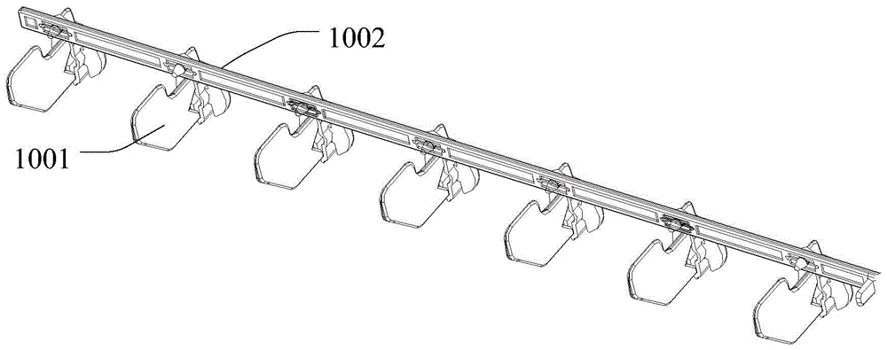
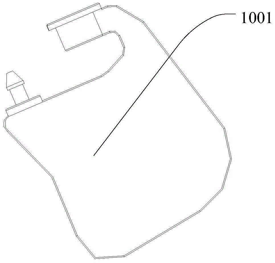
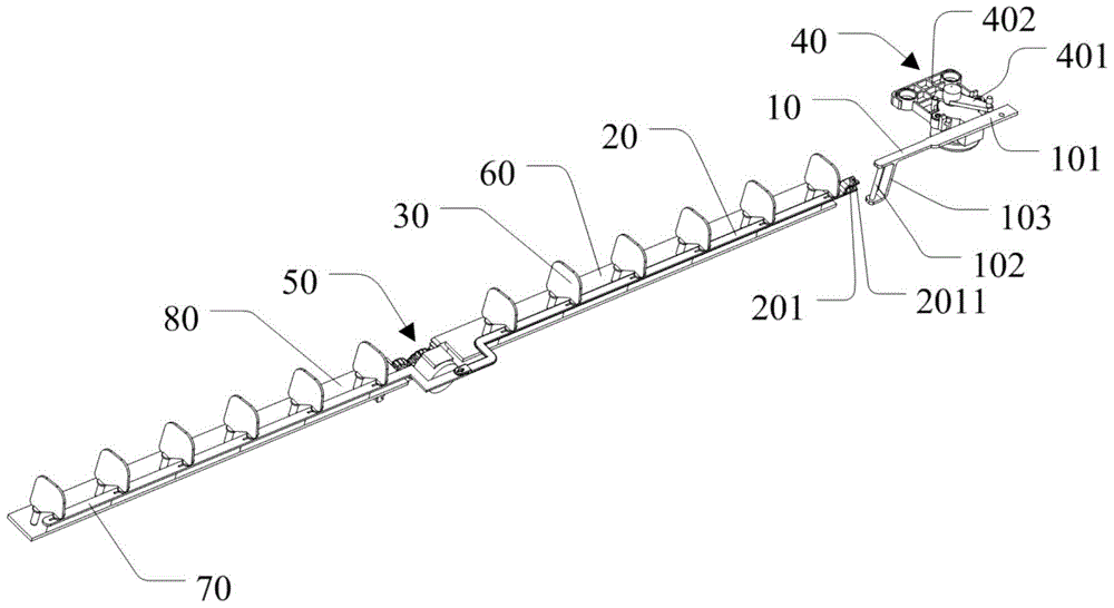
[0043] refer to Figure 3 to Figure 6 , image 3 It is a structural schematic diagram of an embodiment of the transmission device of the present invention; Figure 4 yes image 3 Schematic diagram of the structural state of another viewing angle of the transmission device shown; Figure 5 yes image 3 Partial structural schematic diagram of the transmission device shown; Image 6 It is a structural schematic diagram of an embodiment of the second connecting rod of the transmission device of the present invention;

[0044] The first connecting rod 10 includes a driving rod 101 and a first sliding part 102 ar...


PUM


Abstract

The invention discloses a transmission device and an air conditioner comprising the transmission device. The transmission device comprises a first connecting rod, a second connecting rod, air guiding blades and a horizontal transmission mechanism. A second sliding part of the second connecting rod is slidably connected with a first sliding part of the first connecting rod, and the horizontal transmission mechanism drives the air guiding blades connected to the second connecting rod to perform lateral deflection through the first connecting rod. When the air guiding blades perform longitudinal movement up and down in air outlet, the air guiding blades are adjusted to the appropriate position according to a running mode of the air conditioner so as to overcome influence on wind direction adjustment caused by adjustment of density difference between air flow and indoor air. Simultaneously, when left and right swing is not needed, the air guiding blades can all descend into an air conditioner base below the air outlet to be hidden; simultaneously, when swing is not needed, the air guiding blades can move downwards until the air guiding blades are hidden; the air conditioner is intelligently controlled to supply air in a three-dimensional mode through the transmission device, manual poking is not needed, and accidents in the operation process are avoided.

Description

technical field [0001] The invention relates to the field of air conditioners, in particular to a transmission device of the air conditioner and an air conditioner comprising the transmission device. Background technique [0002] The air guide mechanism of the indoor unit of the wall-mounted air conditioner is divided into a vertical air guide plate and a horizontal air guide vane. Make adjustments. [0003] In the existing technology, such as figure 1 and figure 2 as shown, figure 1 It is a structural schematic diagram of an embodiment of the connecting rod device in the prior art; figure 2 It is a structural schematic diagram of an embodiment of the horizontal guide vane of the connecting rod device in the prior art; the horizontal guide vane 1001 is connected into a group through the connecting rod 1002, installed on the side of the air outlet, and the left and right sides can be realized by manually adjusting the position. The direction of the airflow changes in t...

Claims


Application Information

Patent Timeline
Patent Type & Authority Patents(China)
IPC IPC(8): F24F13/10
Inventor 鲁益军王荣转
Owner TCL AIR CONDITIONER ZHONGSHAN CO LTD
Why Eureka
Try Eureka