Air conditioner and its control method

A control method and air-conditioning technology, which is applied in the direction of airflow control components, mechanical equipment, etc., can solve problems such as finger injuries, influence on horizontal guide vanes, and inability to perform lifting adjustments, so as to improve accuracy and avoid accidents

Inactive Publication Date: 2019-04-16
TCL AIR CONDITIONER ZHONGSHAN CO LTD
View PDF8 Cites 0 Cited by
  • Summary
  • Abstract
  • Description
  • Claims
  • Application Information

AI Technical Summary

Problems solved by technology

[0003] In the existing technology, such as figure 1 and figure 2 as shown, figure 1 It is a structural schematic diagram of an embodiment of the connecting rod device in the prior art; figure 2 It is a structural schematic diagram of an embodiment of the horizontal guide vane of the connecting rod device in the prior art; the horizontal guide vanes 1001 are connected into groups through the connecting rod 1002, installed at the air outlet, and the left and right sides are realized by manually adjusting the position. The direction of the airflow changes in the direction. The main function of the inner connecting rod of the air conditioner is to connect the scattered horizontal guide vanes into groups. Deflection, when changing its position manually, people's fingers will touch the cross-flow fan of the air conditioner if they don't pay attention, causing finger injuries
[0004] At the same time, when the air conditioner is in cooling operation, the density of the air conditioner’s regulated airflow is greater than the density of the room air. At this time, the regulated airflow sinks, which affects the adjustment of the wind direction by the horizontal guide vanes, and the horizontal guide vanes need to move downwards to better Three-dimensional air supply; when the air conditioner is in heating operation, the density of the air conditioner’s regulated airflow is lower than that of the room’s air. Perform three-dimensional air supply, but in the prior art, the horizontal air guide vanes are fixed at the air outlet and cannot be adjusted up and down

Method used


Image

  • Air conditioner and its control method
  • Air conditioner and its control method
  • Air conditioner and its control method

Examples


Embodiment Construction

[0046] The technical solutions of the present invention will be further described below in conjunction with the accompanying drawings and specific embodiments. It should be understood that the specific embodiments described here are only used to explain the present invention, not to limit the present invention.

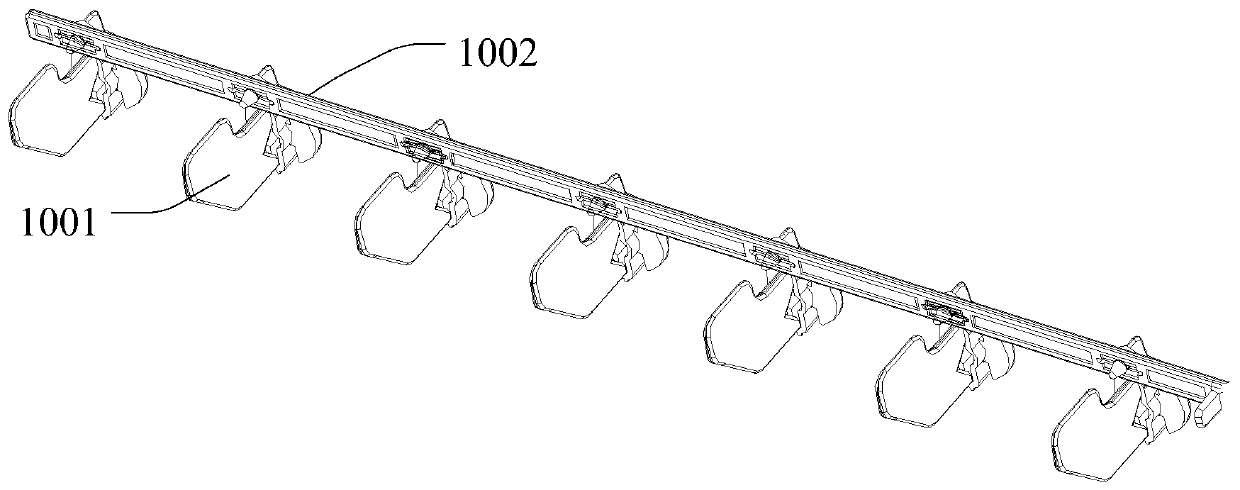
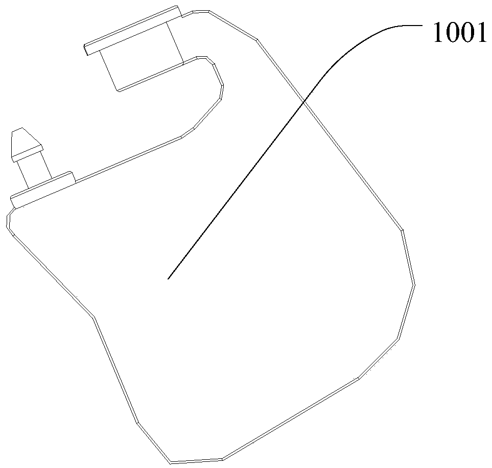
[0047] The invention provides a transmission device.

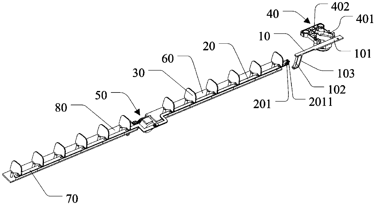
[0048] refer to Figure 3 to Figure 6 , image 3 It is a structural schematic diagram of an embodiment of the transmission device of the present invention; Figure 4 yes image 3 Schematic diagram of the structural state of another viewing angle of the transmission device shown; Figure 5 yes image 3 Partial structural schematic diagram of the transmission device shown; Image 6 It is a structural schematic diagram of an embodiment of the second connecting rod of the transmission device of the present invention;

[0049]The first connecting rod 10 includes a driving rod 101 and a first sliding part 102 arr...


PUM


Abstract

The invention discloses an air conditioner and a method for controlling the same. The air conditioner comprises air guide blades and a longitudinal transmission mechanism. The longitudinal transmission mechanism drives the air guide blades to move longitudinally in an air outlet of the air conditioner. According to the air conditioner and the method for controlling the same, the longitudinal transmission mechanism is used for driving the air guide blades to move longitudinally between the bottom and the top of the air outlet of the air conditioner, and accordingly, positions of the air guide blades in the air outlet are changed; when left and right swinging air is not needed, the air guide blades can be dropped into an air conditioner base below the air outlet to be hidden; the air guide blades can be adjusted to appropriate positions according to the air conditioner running mode so as to overcome effects on air direction adjusting between adjusting air flows and indoor air; intelligent air conditioner three-dimensional air feeding is controlled intelligently instead of manual shifting, accidents during the operation are prevented, and the air direction adjusting accuracy of air flows entering the air conditioner is improved.

Description

technical field [0001] The invention relates to the field of air conditioners, in particular to an air conditioner and a control method for the air conditioner. Background technique [0002] The air guide mechanism of the indoor unit of the wall-mounted air conditioner is divided into a vertical air guide plate and a horizontal air guide vane. Make adjustments. [0003] In the existing technology, such as figure 1 and figure 2 as shown, figure 1 It is a structural schematic diagram of an embodiment of the connecting rod device in the prior art; figure 2 It is a structural schematic diagram of an embodiment of the horizontal guide vane of the connecting rod device in the prior art; the horizontal guide vanes 1001 are connected into a group through the connecting rod 1002, installed at the air outlet, and the left and right sides are realized by manually adjusting the position. The direction of the airflow changes in the direction. The main function of the inner connect...

Claims


Application Information

Patent Timeline
Patent Type & Authority Patents(China)
IPC IPC(8): F24F13/10F24F11/79
Inventor 鲁益军王荣转
Owner TCL AIR CONDITIONER ZHONGSHAN CO LTD
Why Eureka
Try Eureka