
Light emitting diode pixel unit circuit, its driving method and display panel

A technology of light-emitting diodes and pixel units, applied in circuits, electrical components, static indicators, etc., can solve the problem of losing the threshold voltage compensation function and achieve the effect of threshold voltage compensation

Active Publication Date: 2016-01-06
BOE TECH GRP CO LTD +1
View PDF4 Cites 0 Cited by
  • Summary
  • Abstract
  • Description
  • Claims
  • Application Information

AI Technical Summary

Problems solved by technology

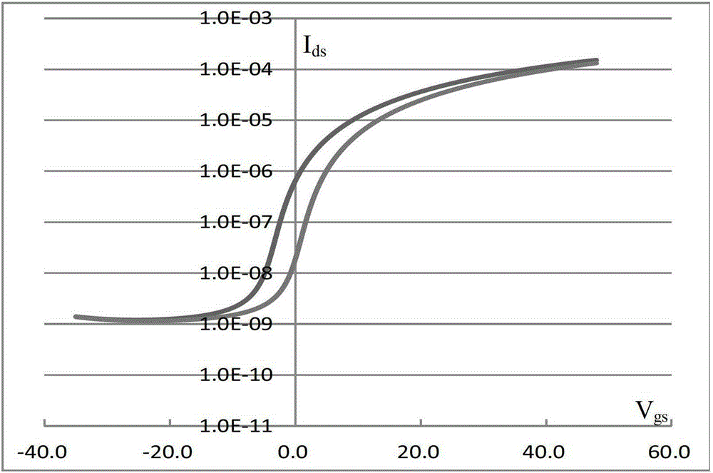
[0005] To sum up, if the depletion-type TFT adopts the traditional N-type TFT AMOLED pixel drive circuit design, when the diode connection method is used to compensate the threshold voltage, since the threshold voltage is negative, before the TFT enters the sub-threshold saturation cut-off, the source-drain voltage is zero and cuts off early, thus losing the threshold voltage compensation function

Method used


Image

  • Light emitting diode pixel unit circuit, its driving method and display panel
  • Light emitting diode pixel unit circuit, its driving method and display panel
  • Light emitting diode pixel unit circuit, its driving method and display panel

Examples


Embodiment 1

[0031] see Figure 5 An active matrix organic light emitting diode AMOLED pixel unit circuit provided by an embodiment of the present invention includes: a light emitting module 50, a driving module 51, a light emitting control module 52, a threshold compensation module 53, a data voltage writing module 54 and an initialization module 55 ;in,

[0032] A driving module 51, configured to drive the light emitting module 50;

[0033] A light emitting control module 52, configured to control whether the light emitting module 50 emits light;

[0034] A threshold compensation module 53, configured to perform threshold voltage compensation on the drive module 51;

[0035] The data voltage writing module 54 is used to input the data voltage to the driving module 51;

[0036] The initialization module 55 is configured to initialize the threshold compensation module 53 .

[0037] Preferably, the drive module 51 includes a first transistor T1, the gate of which is connected to the fir...

Embodiment 2

[0052] see Figure 9 Another active matrix organic light emitting diode AMOLED pixel unit circuit provided by an embodiment of the present invention includes: a light emitting module 80, a driving module 81, a light emitting control module 82, a threshold compensation module 83, a data voltage writing module 84 and an initialization module 85; of which,

[0053] A driving module 81, configured to drive the light emitting module 80;

[0054] A light emitting control module 82, configured to control whether the light emitting module 80 emits light;

[0055] A threshold compensation module 83, configured to perform threshold voltage compensation on the drive module 81;

[0056] The data voltage writing module 84 is used to input the data voltage to the driving module 81;

[0057] The initialization module 85 is configured to initialize the threshold compensation module 83 .

[0058] Preferably, the drive module 81 includes a first transistor T1, the gate of which is connected...


PUM


Abstract

Disclosed are an active matrix organic light-emitting diode (AMOLED) pixel unit circuit, a drive method therefor and a display panel, which are used for realizing threshold voltage compensation. The AMOLED pixel unit circuit comprises a light-emitting module; a drive module used for driving the light-emitting module; a light-emitting control module used for controlling the light-emitting module to emit light; a threshold compensation module used for performing threshold voltage compensation on the drive module; a data voltage writing module used for inputting a data voltage to the drive module; and an initialization module used for initializing the threshold compensation module. By way of improving a pre-charging manner, a gate electrode for driving a TFT is fixedly set at a data level which is lower than a high level, thereby realizing threshold voltage compensation when entering a sub threshold saturation cut-off state before a source-drain voltage is zero at a compensation stage.

Description

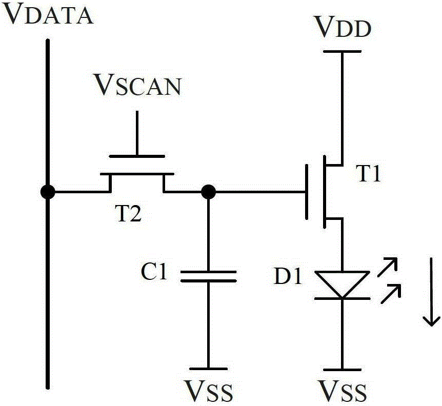
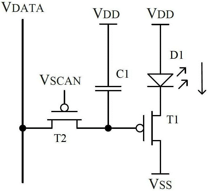
technical field [0001] The invention relates to the field of display technology, in particular to a light emitting diode pixel unit circuit, a driving method thereof and a display panel. Background technique [0002] In the field of display technology, active matrix organic light emitting diode (ActiveMatrixOrganicLightEmittingDiode, AMOLED) display device is characterized by its ultra-thin, good shock resistance, large viewing angle, short response time, good low temperature, high luminous efficiency, and can be made into flexible displays, etc. Many advantages have gradually attracted people's attention. Figure 1(a) is the basic pixel circuit structure of an N-type thin film transistor (ThinFilmTransistor, TFT) driving an active matrix organic light emitting diode (ActiveMatrixOrganicLightEmittingDiode, AMOLED) in the prior art, and Figure 1(b) is a P-type in the prior art TFT drives AMOLED basic pixel circuit structure. VDATA in Figure 1(a) and Figure 1(b) is a data lev...

Claims


Application Information

Patent Timeline
Patent Type & Authority Patents(China)
IPC IPC(8): G09G3/3258H01L27/32
CPCG09G3/3233G09G2300/0814G09G2300/0819G09G2320/045
Inventor 谭文祁小敬
Owner BOE TECH GRP CO LTD
Learn More